X" - 3/4" = ride height – JKS 2200 User Manual
Page 3
JKS2200
JKS Adjustable Coil Spacer Installation
Page 3
Cut away the lower portion of bump stop holder
until even with bottom of flat washer. DO NOT CUT
OFF FLAT WASHER! HINT: A die grinder with cut-
off wheel or reciprocating saw is useful for cutting
bump stop holder.
Grind away any remaining portion of bump stop
holder that protrudes beyond flat washer. At the
same time, remove any debris from surface of
flat washer. HINT: A grinding wheel is useful for
removing any additional material or debris.
Insert a 10mm x 1.5p tap straight into the flat
washer to form a threaded hole. The hole in flat
washer should be the correct size. If not, enlarge
the hole according to the size indicated on the tap.
Remove the rubber isolator pad from the upper
spring mount.
Paint any exposed metal to prevent corrosion.
3. INSTALL ACOS ON SPRING MOUNT
Rotate the Transfer Ring (A) until inner threads are
even with top edge of Threaded Tube (C).
Slide the pre-assembled ACOS unit all the way on
to the upper spring mount. If necessary, remove
any debris or obstructions that prevent Threaded
Tube (C) from seating cleanly against top surface
of upper spring mount.
HINT: Transfer Ring (A) should not make contact
with upper spring mount at this time. If necessary,
adjust Transfer Ring away from top surface of
spring mount.
Apply anti-seize lubricant to the 10mm x 55mm
Cap Bolt (G) and insert through Bump Stop (F) and
Bump Stop Support (E). Thread bolt completely
into hole in the center of upper spring mount, but
do NOT tighten.
HINT: Raised surface of Bump
Stop Support (E) must face up and fully engage
bottom of Threaded Tube (C).
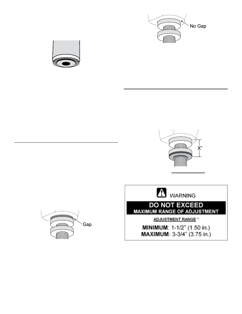
Now rotate the Transfer Ring (A) up until it con-
tacts the flat surface above it.
Unthread the 10mm x 55mm Cap Bolt (G) a few
turns so Threaded Tube (C) can be lowered
slightly. Then rotate the Transfer Ring (A) one-half
turn up towards flat surface above.
Slowly tighten 10mm x 55mm Cap Bolt (G) into
the coil spring mount until sides of Bump Stop (F)
begin to bulge. Do NOT overtighten!
4. SET ADJUSTER RING FOR DESIRED
RIDE HEIGHT
Once the Adjustable Coil Spacer is installed, front ride
height is determined by measuring the distance be-
tween top of Transfer Ring (A) and bottom of Isolator
Pad (D), and subtracting 3/4” (0.75 in.).
'X" - 3/4" = RIDE HEIGHT*
*Represents Increase in ride height over OE Suspension
Apply spray lubricant to Threaded Tube (C) and
rotate Adjuster Ring (B) to desired position.
Tighten recessed bolt in Adjuster Ring (B) to lock
in position.