Installation, Ports and connections, Communication – Ag Leader GPS 1600 Operators Manual User Manual
Page 6: Radar-simulated pulse output, Mounting the receiver, Selecting the proper antenna location, Ports and connections communication, Nstallation, Orts, Onnections
2
PN 2006346 Rev A
1600 R
ECEIVER
I
NSTALLATION
P
ORTS
AND
C
ONNECTIONS
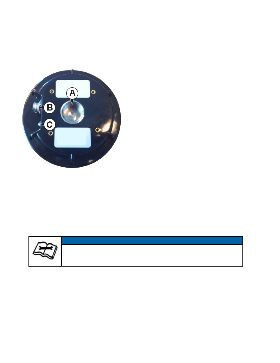
(A) Mounting Hole - Pole or tripod mount, marine 1”
standard, adaptable to 5/8” (adapter included)
(B) Power, data port (12-pin) - External power/data
cable; allows you to supply power as well as
communicate with external devices via CAN, NMEA
0183 serial, and binary
(C) LED Display - provides system information based on
the color and pulse of the LED as follows:
Red LED = power on
Amber LED = GPS lock
Green LED = DGPS position
All connections and ports are located on the bottom of
the unit, as shown.
C
OMMUNICATION
The receiver supports radar-simulated pulse output and various NMEA 2000 messages.
R
ADAR
-S
IMULATED
P
ULSE
O
UTPUT
The radar-simulated pulse output provides accurate ground speed. The receiver uses pin 12 for the
speed out pin. Pin 12 will output a square wave with a 50% duty cycle and the frequency of the square
wave varies directly with speed. 94 Hz represents a speed of 1 m/sec (or 28.65 pulse/foot traveled).
M
OUNTING
THE
R
ECEIVER
S
ELECTING
THE
P
ROPER
A
NTENNA
L
OCATION
Proper antenna placement is critical to positioning accuracy.
To select the proper antenna location:
• Place the antenna with an unobstructed view of the sky. An obstructed view of the sky may impair system
performance. The GPS engine computes a position based on measurements from each satellite to the
internal GPS receiver.
NOTE
Pin 12 does not have any form of isolation or surge protection. It is strongly
recommended that you incorporate some form of isolation circuitry into your
supporting hardware if you want to utilize the Speed Radar Pulse output.