HP 3Gb SAS Switch for HP BladeSystem c-Class User Manual
Page 8
For the c7000 BladeSystem enclosure, use the following table to determine which external storage enclosures
to use when zoning the external storage to the server blades.
For example, as shown in the table, if a full-height server blade is installed in device bay 1-8 of a c7000
enclosure, and the P700m Controller is installed in server mezzanine slot 2; the 3Gb SAS BL Switch must
be installed in BladeSystem interconnect bay 5, 6, 7, or 8 and it should be assigned a zone group that is
in an external storage enclosure attached to 3Gb SAS BL Switch ports 1, 2, 3, or 4.
Zone groups must be in
storage enclosures
nl
connected to these 3Gb
SAS BL Switch ports
BladeSystem
nl
c-Class
nl
interconnect bay
BladeSystem
nl
c-Class
nl
device bay
Mezzanine slot
Server type
BladeSystem
nl
c-Class
nl
enclosure
nl
model
1 – 4
3/4
1 – 8
1
Half height
c7000
5 – 8
3/4
9 – 16
1 – 4
5/6/7/8
1 – 8
2
5 – 8
5/6/7/8
9 – 16
1 – 4
3/4
Any
1
Full height
1 – 4
5/6/7/8
Any
2
5 – 8
5/6/7/8
Any
3
1 – 4
5/6
1A – 8A
Any
Half height
nl
Double dense
nl
(BL2x220c)
1 – 4
7/8
1B – 8B
5 – 8
5/6
9A – 16A
5 – 8
7/8
9B – 16B
1 – 4
3/4
Any
1
Full height
nl
Double wide
nl
(BL680c G7)
1 – 4
5/6/7/8
Any
2
5 – 8
5/6/7/8
Any
3
1 – 4
5/6/7/8
Any
4
5 – 8
3/4
Any
5
5 – 8
5/6/7/8
Any
7
As shown in the tables, each HP 3Gb SAS BL Switch is organized in two sets of connections. These two
connection sets are based on the two SAS expanders housed in the switch. Each SAS expander provides
four external SAS ports and is connected internally to eight blade bays. This organization may have
implications for best system configuration practices according to the hardware in use.
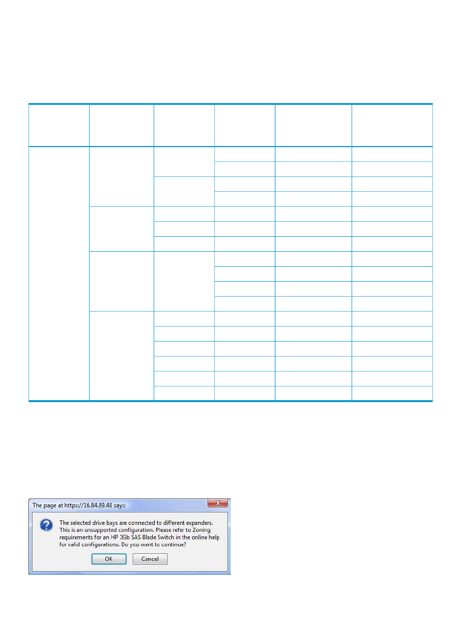
The VSM GUI displays the following warning message if a configuration is attempted that violates these
requirements. All such configurations are unsupported by HP.
8