Connector pinouts – HP NetRAID 1 Controller User Manual
Page 69
65
Connector Pinouts
High-Density 68-Pin SCSI Connector and P-Cable Single-
Ended Cable Pinout
High-Density Connector
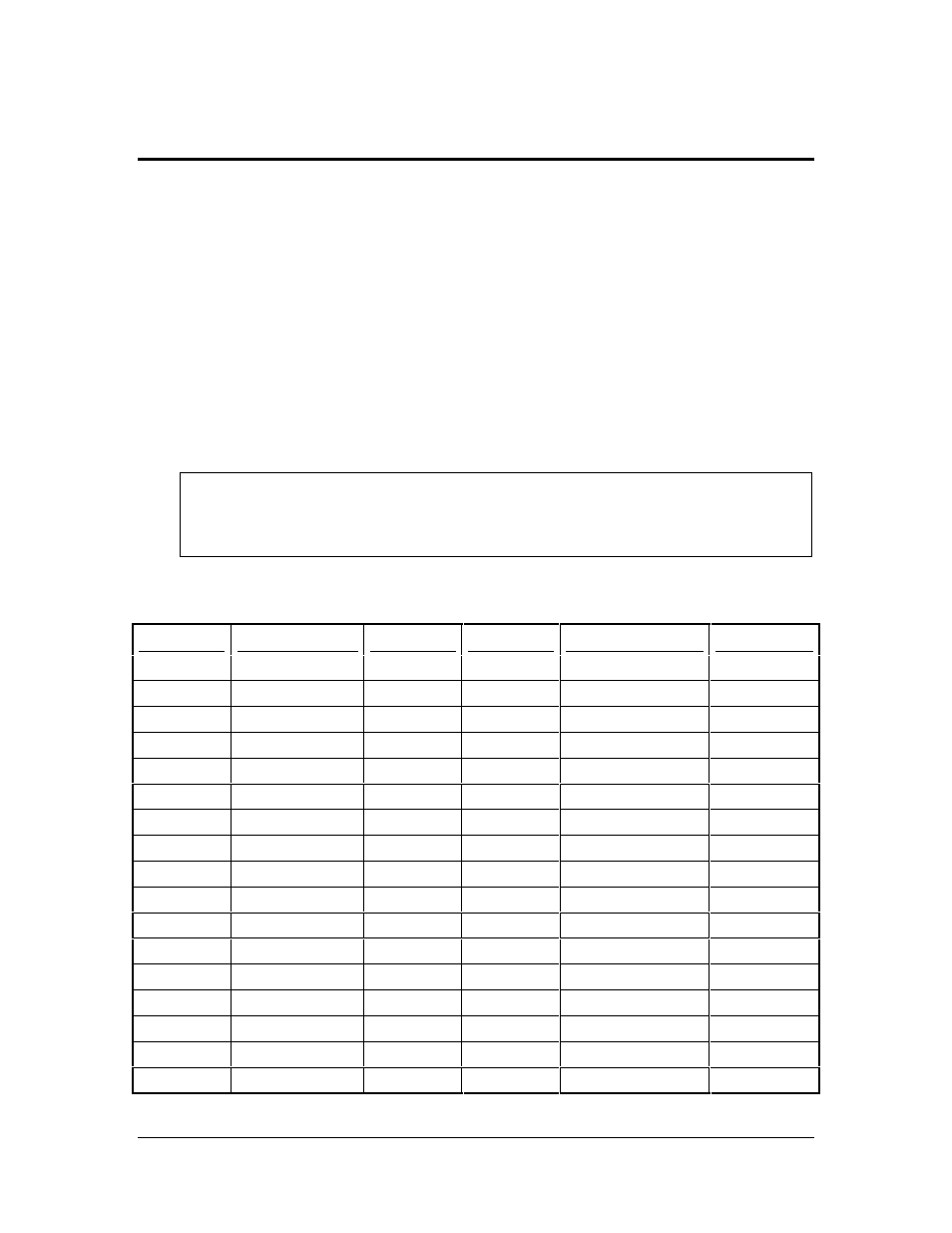
The following facts apply to the information in the High-Density SCSI connector table below:
•
A hyphen before a signal name indicates that signal is active low.
•
The connector pin refers to the conductor position when using 0.025 inch centerline flat
ribbon cable with a high-density connector (AMPLIMITE .050 Series connectors).
•
Eight-bit devices connected to the P-Cable must leave the following signals open: -dB (8),
-dB (9), -dB (10), -dB (11), -dB(12), -dB (13), -dB (14), -dB 15), and -dB (P1).
CAUTION
Lines labeled RESERVED should be connected to GROUND in the bus
terminator assemblies or in the end devices on the SCSI cable.
RESERVED lines should be open in the other SCSI devices, but can be
connected to GROUND.
All other signals should be connected as defined.
Signal
Connector Pin
Cable Pin
Cable Pin
Connector Pin
Signal
GROUND
1
1
2
35
-dB(12)
GROUND
2
3
4
36
-dB(13)
GROUND
3
5
6
37
-dB(14)
GROUND
4
7
8
38
-dB(15)
GROUND
5
9
10
39
-dB(P1)
GROUND
6
11
12
40
-dB(0)
GROUND
7
13
14
41
-dB(1)
GROUND
8
15
16
42
-dB(2)
GROUND
9
17
18
43
-dB(3)
GROUND
10
19
20
44
-dB(4)
GROUND
11
21
22
45
-dB(5)
GROUND
12
23
24
46
-dB(6)
GROUND
13
25
26
47
-dB(7)
GROUND
14
27
28
48
-dB(P)
GROUND
15
29
30
49
GROUND
GROUND
16
31
32
50
GROUND
TERMPWR
17
33
34
51
TERMPWR