Rear panel leds and buttons, Base enclosure – HP 9000 Virtual Library System User Manual
Page 192
Description
Item
SAS port 1, output port
6
Power module 1
7
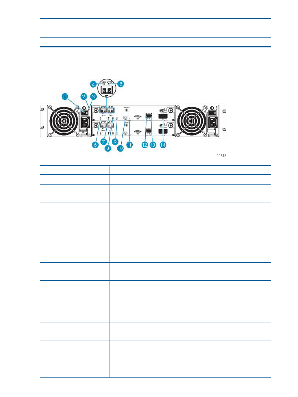
Rear Panel LEDs and Buttons
Base Enclosure
Status
Description
Item
Toggle, where O is Off.
Power switch
1
1
Green = AC power is on and input voltage is normal.
AC Power Good LED
2
Off = AC power is off or input voltage is below the minimum threshold.
Yellow = DC output voltage is out of range or a fan is operating below the minimum
required RPM.
DC-Fan Fault/ Service
Required LED
3
Off = DC output voltage is normal.
Green = The port link is connected.
FC link status (L) LED
4
Off = The port is empty or the link is down.
Green = The data transfer rate is 4 Gbps.
FC link speed (S) LED
5
Off = The data transfer rate is 2 Gbps.
Blinking white = RAID controller is selected (for identification purposes only).
Unit locator LED
6
Off = Not active.
Blue = The RAID controller can be removed.
OK to remove LED
7
Off = The RAID controller is not prepared for removal.
Yellow = A fault has been detected or a service action is required.
Fault/Service required
LED
8
Blinking yellow = A hardware-controlled power on or a cache flush or restore error
occurred.
Green = RAID controller is operating normally.
Power On/OK LED
9
Off = RAID controller is not OK.
Green = Cache is dirty (contains unwritten data) and operation is normal.
Cache status LED
10
Blinking green (1 Hz) = A Compact Flash flush is in progress.
Blinking green (10 Hz) = A cache self-refresh is in progress. Valid data will remain
until supercaps have drained, approximately 15 minutes.
Off = Cache is clean (contains no unwritten data).
192 Component Identification