Front panel leds and buttons – HP 9000 Virtual Library System User Manual
Page 183
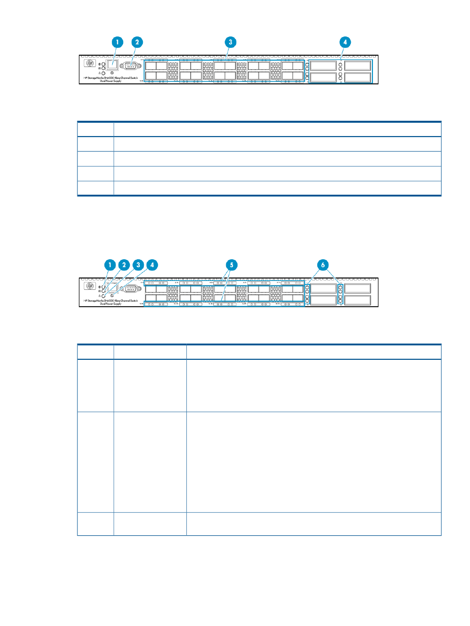
Description
Item
Ethernet port
1
Serial port
2
Fibre Channel ports
3
XPAK transponder ports (not in use)
4
Front Panel LEDs and Buttons
This section provides images and descriptions of the front panel LEDs and buttons of the Fibre
Channel Switch 8/20q.
Status
Description
Item
Green = The switch is receiving power.
Input Power LED
1
Off = One of these conditions exist:
•
The switch is NOT receiving power.
•
The switch is in maintenance mode.
Green = The switch is in maintenance mode.
Heartbeat LED
2
Blinking green (once per second) = the switch is operational.
Other blink patterns indicate critical errors:
•
2 blinks — internal firmware failure
•
3 blinks — Fatal power-on self test error
•
4 blinks — configuration file system error
•
5 blnks — over-temperature
A critical error also illuminates the System Fault LED.
Amber = a fault exists in the switch firmware or hardware. See the Heartbeat LED
blink pattern for details.
System Fault LED
3
Fibre Channel Switch 8/20q Components, LEDs, and Buttons 183