Setup – HP Designjet 3D Printer series User Manual
Page 21
17
Setup
19.
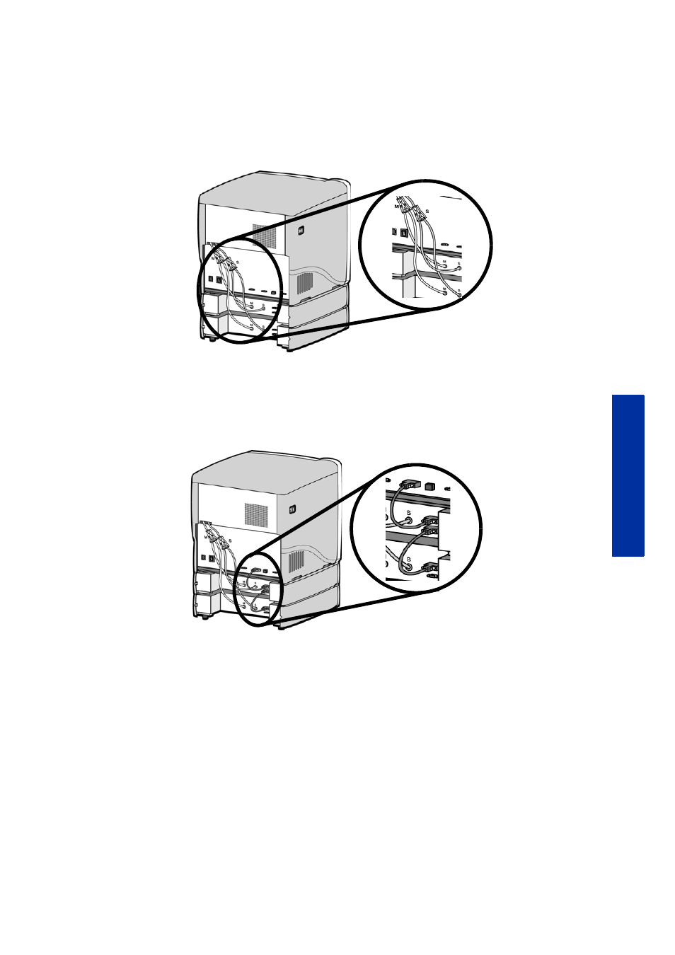
Connect the long red striped material tube (M2) from model (M) coupler of lower material
bay to right side of model Y block by inserting firmly into red couplers. Gently pull the
tube to ensure it is properly inserted.
20.
Repeat with long black striped (S2) material tube for support side. See
Figure 13
Connecting the long material tubes
21.
Connect a material bay cable between the printer and the top connector on the upper
material bay.
22.
Connect the other material bay cable between the bottom connector of the upper material
bay to the top connector of the lower material bay. See
Figure 14
Connecting the material bay cables
23.
Connect the power cable and network cable.
24.
Switch the circuit breaker to the ON position.
25.
Power the printer ON at the power switch.
26.
After the printer has booted up, you may need to reload the printer firmware. If the printer
displays “Send Upgrade from Workstation”,
See “Updating printer firmware:” on page 32.
27.
Insert model and support material spools into the new material carriers.
28.
From display panel press Material. Display will show Add/Remove.
29.
Open material bay doors and push both red handled model carriers into right side of the
material bays until they latch.
30.
Push both black handled support carriers into left side of the material bays until they latch.