Figure 7-3, Sample system diagram: g-series rvu – HP NonStop G-Series User Manual
Page 143
Balancing and Tuning a System
Measure User’s Guide — 520560-003
7 -7
Learning About the System and Its Applications
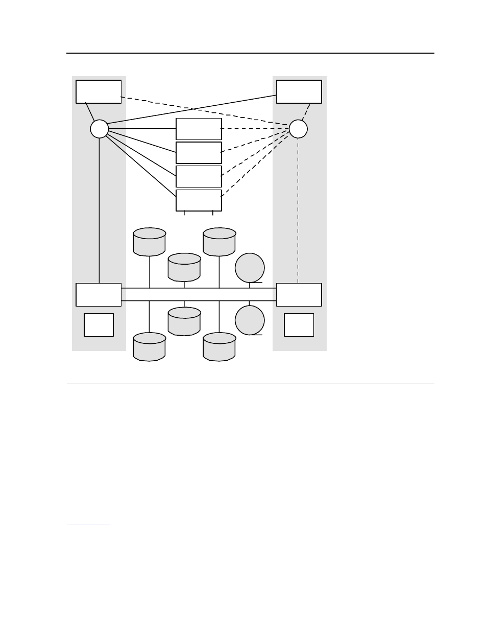
You should also develop a diagram of each major application running on the system.
Each application diagram should reflect these system elements:
•
Requesters
•
Servers
•
Data files, including how the file is structured and accessed, where the file is
located, whether it can be moved, and whether it can be partitioned
•
Paths between requesters, servers, and files. Include the approximate number of
messages over each path.
on page 7-8 shows a sample application diagram.
Figure 7-3. Sample System Diagram: G-Series RVU
Processor
X
Y
SCSI
SACs
PMF
CRU
Disks
$SYSTEM-M
$TAPE
Processor
X
Y
SCSI
SACs
PMF
CRU
CCSA
$DATA-P
$AUDIT-P
$SYSTEM-P
$TAPE2
$DATA-M
$AUDIT-M
TRSA
FESA
E3S5A
$NET1 $NET2
X
Y
VST005.vsd
- xt1500 (58 pages)
- LaserJet 4700 (68 pages)
- ProLiant BL460c Gen8 Server Blade (67 pages)
- ProLiant DL360 Server (16 pages)
- ProLiant BL460c Gen8 Server Blade (65 pages)
- ProLiant DL388p Gen8 Server (128 pages)
- ProLiant BL465c Server Blade (87 pages)
- ProLiant DL388p Gen8 Server (47 pages)
- ProLiant BL40p Server series (73 pages)
- ProLiant ML115 Server (63 pages)
- ProLiant DL140 G2 Server (81 pages)
- Servidor HP ProLiant ML370 G4 (20 pages)
- Servidor HP ProLiant ML370 G4 (30 pages)
- Servidor HP ProLiant DL160 G5p (84 pages)
- Servidor HP ProLiant DL980 G7 (143 pages)
- Servidor HP ProLiant DL380 G5 (137 pages)
- Integrity rx2620 Servers (24 pages)
- Integrity rx2620 Servers (33 pages)
- Integrity rx2620 Servers (100 pages)
- Integrity rx2620 Servers (37 pages)
- Integrity Superdome sx1000 Server (53 pages)
- Integrity rx2620 Servers (37 pages)
- Integrity rx2620 Servers (58 pages)
- Integrity rx2620 Servers (77 pages)
- Integrity rx2620 Servers (107 pages)
- Integrity rx2620 Servers (55 pages)
- 9000 rp3440 Servers (36 pages)
- Integrity rx2620 Servers (42 pages)
- Integrity rx2620 Servers (48 pages)
- Integrity rx2620 Servers (53 pages)
- Servidor HP ProLiant DL360p Gen8 (129 pages)
- Servidor HP ProLiant DL120 G6 (133 pages)
- ProLiant DL580 Gen8 Server (91 pages)
- ProLiant MicroServer Gen8 (95 pages)
- ProLiant MicroServer (94 pages)
- ProLiant BL685c G5 Server Blade (99 pages)
- ProLiant Firmware Maintenance CD (87 pages)
- ProLiant BL10e Server Blade (232 pages)
- ProLiant BL40p Server series (30 pages)
- Serveur lame HP ProLiant BL680c G5 (90 pages)
- Serveur lame HP ProLiant BL465c Gen8 (578 pages)
- ProLiant DL320e Gen8 Server (96 pages)
- ProLiant ML110 G7 Server (113 pages)
- 9000 rp8420 Servers (38 pages)
- Integrity Superdome sx1000 Server (19 pages)