American Dryer Corp. AD-15 Phase 7 User Manual
Page 8
6
American Dryer Corp.
113243-1
CAUTION:
This dryer produces combustible lint and must
be exhausted to the outdoors.
When possible, it is suggested to provide a separate (single)
exhaust duct for each dryer.
CAUTION:
IMPROPERLY SIZED OR INSTALLED
EXHAUST DUCTWORK CAN CREATE A
POTENTIAL FIRE HAZARD.
The exhaust ductwork should be laid out in such a way that
the ductwork travels as directly as possible to the outdoors
with as few turns as possible. The shape of the ductwork is
not critical provided that the minimum cross section area is
maintained. Single or independent dryer venting is
recommended.
It is suggested that the use of 90° turns be avoided; use 30°
or 45° angles instead.
The ductwork should be smooth inside with no projections
from sheet metal screws or other obstructions, which will
collect lint. When adding ducts, the ducts to be added should
overlap the duct to which it is connected. ALL ductwork joints
must be taped to prevent moisture and lint from escaping
into the building. Additionally, inspection doors should be
installed at strategic points in the exhaust ductwork for
periodic inspection and cleaning.
IMPORTANT:
When connecting ductwork to the dryer exhaust
duct, be sure that when screws are used they
DO NOT restrict the operation (both opening
and closing) of the damper.
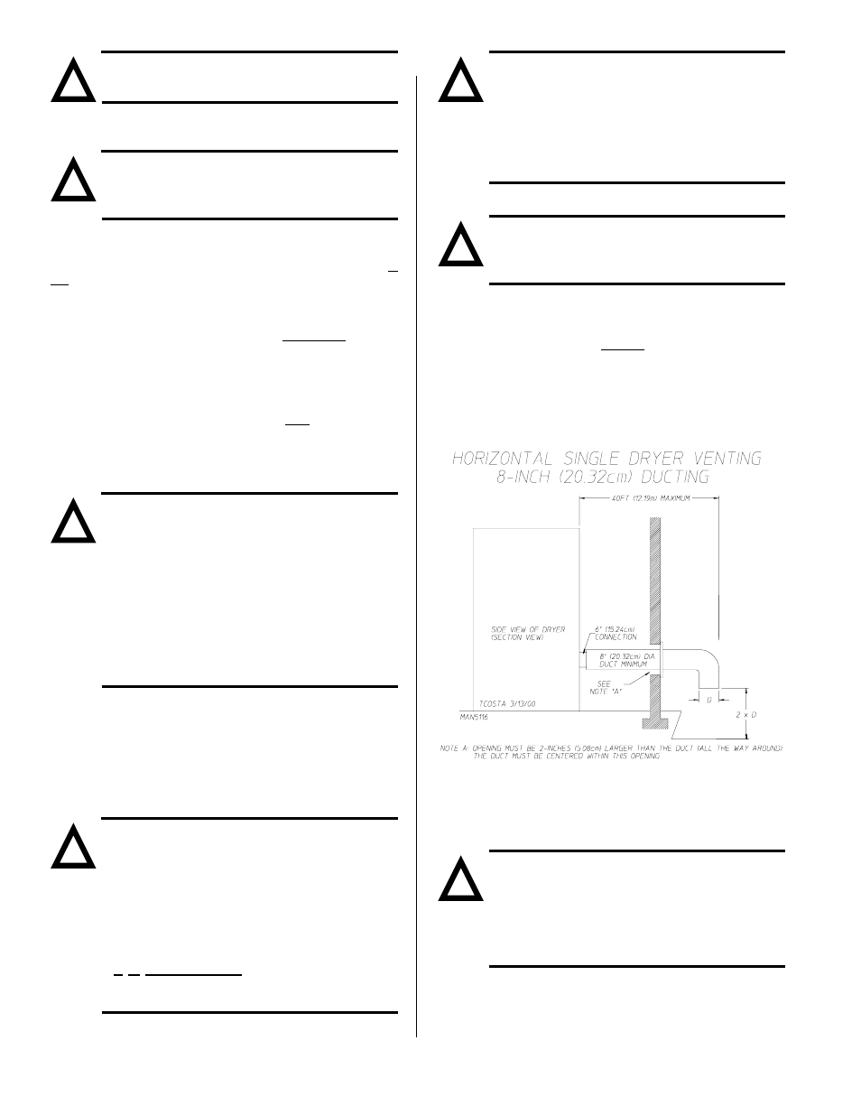
NOTE:
When the exhaust ductwork passes through a
wall, ceiling, or roof made of combustible
materials, the opening must be 2-inches (5.08
cm) larger than the duct (all the way around).
The duct must be centered within this opening.
To protect the outside end of the horizontal ductwork from the
weather, a 90° elbow bent downward should be installed
where the exhaust exits the building. If the ductwork travels
vertically up through the roof, it should be protected from the
weather by using a 180° turn to point the opening downward.
In either case, allow at least twice the diameter of the duct
between the duct opening and the nearest obstruction (i.e.,
roof or ground level).
IMPORTANT:
DO NOT use screens, louvers, or caps on the
outside opening of the exhaust ductwork.
Exhaust back pressure measured by a
manometer at the dryer exhaust duct area must
be no less than 0 and must not exceed 0.3
inches (0.74 mb) of water column (W.C.).
It is recommended that exhaust or booster
fans not be used in the exhaust ductwork
system.
NOTE:
As per the National Fuel Gas Code, Exhaust
ducts for type 2 clothes dryers shall be
constructed of sheet metal or other
noncombustible material. Such ducts shall be
equivalent in strength and corrosion resistance
to ducts made of galvanized sheet steel not less
than 0.0195-inches (26 gauge [0.05 mm]) thick.
SINGLE DRYER VENTING
IMPORTANT:
For exhaust duct runs over 40 feet (12.19
meters) a minimum size of 10-inches (25.4 cm)
must be used.
HORIZONTAL VENTING
When horizontal single 8-inch (20.32 cm) venting is used,
the ductwork to the outlet cannot exceed 40 feet (12.19
meters), refer to Illus. A below. This calculation of 40 feet
(12.19 meters) compensates or allows for the use of a
maximum of only one (1) elbow (which is the outside outlet
protection).
Illus. A
If the length of the duct run or quantity of elbows used exceeds
the above noted specifications, the cross section area of the
ductwork must be increased in proportion to the number of
elbows or duct run added.
IMPORTANT:
For extended ductwork runs, the cross section
area of the duct can only be increased to an
extent. For extended ductwork runs, a
professional heating, ventilating, and
air-conditioning (HVAC) firm should be
consulted for proper venting information.
!
!
!
!
!
!
!