S.a.f.e. system in action – American Dryer Corp. AD-15 Phase 7 User Manual
Page 27
113243-1
www.amdry.com
25
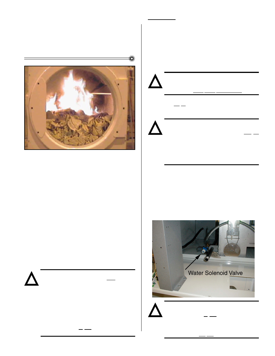
The exclusive Sensor Activated Fire Extinguishing (S.A.F.E.)
System will extinguish fires that may start in the drying basket
(tumbler). A series of sensors positioned throughout the
basket (tumbler) and interfaced with the microprocessor will
trigger the S.A.F.E. system water jet(s) to quickly extinguish
the flames. The water jet(s) remain on for 2 minutes and will
automatically activate again if a fire condition remains or
reignites. While the water jet(s) are activated, the basket
(tumbler) will jog to move the water throughout the load. The
microprocessor will display that the system was activated
and will continue to display until the dryer is attended to.
We have tried to make this manual as complete as possible
and hope you will find it useful. ADC reserves the right to
make changes from time to time, without notice or obligation,
in prices, specifications, colors, and material, and to change
or discontinue models.
BEFORE YOU START!
CHECK LOCAL CODES AND PERMITS
Call your local water company or the proper municipal
authority for information regarding local codes.
IMPORTANT:
It is your responsibility to have ALL plumbing
connections made by a qualified professional
to assure that the plumbing installation is
adequate and conforms to local, state, and
federal regulations or codes.
It is the installation or owners responsibility to
see that the necessary or required water, water
pressure, pipe size, or connections are provided.
Manufacturer assumes no responsibility if the
S.A.F.E. system is not connected, installed,
or maintained properly.
SENSOR ACTIVATED
FIRE EXTINGUISHING
(S.A.F.E.) SYSTEM
S.A.F.E. SYSTEM IN ACTION
INSTALLATION
Requirements
The S.A.F.E. system must be supplied with a minimum water
pipe size of 1/2 and be provided with 40 psi +/- 20 psi (2.75
bar +/- 1.37 bar) of pressure. For use of optional manual
bypass, a second source with the same piping and pressure
requirements is required.
Flexible 1/2 feeds must be provided to avoid damage to
electric water solenoid valve by vibration.
IMPORTANT:
Flexible supply line/coupling must be used.
Solenoid valve failure due to hard plumbing
connections WILL VOID WARRANTY.
If the rear area of the dryer, or the water supply is located in an
area where it will be exposed to cold/freezing temperatures,
provisions must be made to protect these water lines from
freezing.
WARNING:
If the water in the supply line or water solenoid
valve freezes, the S.A.F.E. system will be
INOPERATIVE!!
IMPORTANT:
Appliance is to be connected to the water mains
using a new hose-set and the old hose-sets
should not be reused.
Water Connections:
The water connection is made to the 3/4-11.5 NH hose
adapter of the electric water solenoid valve, located at the
rear upper midsection of the dryer (refer to the photo).
The water solenoid valve has a 3/8 M.P.T. connection supplied
with a 3/4-11.5 NH hose adapter to provide the minimum 1/
2-inch supply (feed) line. Flexible supply line/coupling must
be used in an effort to avoid damaging the electric water
solenoid valve.
NOTE:
The 3/4-11.5 NH is a standard hose coupling
screw thread. It is not to be confused with
3/4 N.P.T. The sealing of an NH connection is
made with a washer opposed to the mating
threads of an N.P.T. assembly. The two (2)
thread designs are not compatible.
!
!
!
!