Device rs-nagv – NORSTAT Safety Relays User Manual
Page 13
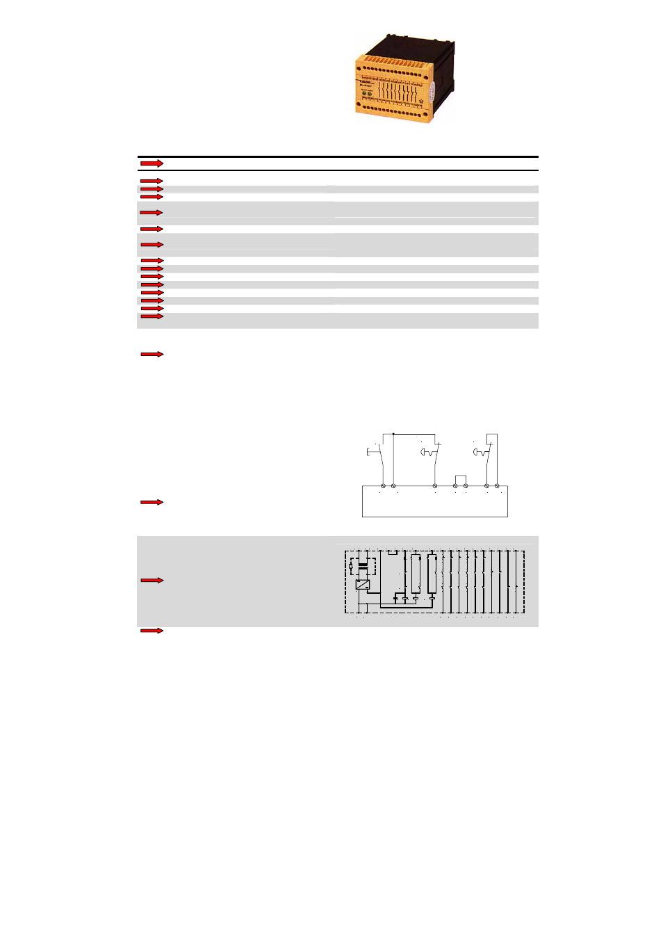
DEVICE
RS-NAGV
Emergency stop
APPLICATIONS
and safety gate monitoring relay
APPROVALS
CE, TÜV, UL, C-UL
CONTACTS
6 normally open safety, 4 normally auxiliary closed
Opposite polarity between channels
SPECIAL CHARACTERISTICS
Cyclial monitoring of the function
LED indicators for status and supply diagnostic
LED
Channel 1 and channel 2
24 V AC / DC (without galvanic disconnection/ safety resistor)
OPERATING VOLTAGE
24 V DC (without galvanic disconnection / electronic fuse),
24, 110-127, 230 V AC (with galvanic disconnection/transformer)
POWER CONSUMPTION
ca. 6 VA
START UP DELAY / FALLBACK TIME
< 200 ms / ca. 30 ms
CONTACT CAPACITY max.
4 A, 240 V AC, 60 V DC
CONTACT CAPACITY min. at 24V DC (*)
10 mA
SIMULTANEITY
Simultaneous protective door contacts : ca. 75 ms
ENVIRONMENTAL TEMPERATURE
- 25°C to + 55°C
SWITCHING CAPACITY
1000 VA (resistive load), 120 W
CONTACT SECURITY
4 A quick acting
OPERATING MODE
(*) We offer all devices who have a CONTACT
CAPACITY of min. 100 mA at 24 V DC with
hard gold-plated contacts. In this way the
CONTACT CAPACITY of min. 100 mA is only 4 mA.
Please ask our sales team!
CONNECTION DIAGRAM
A supply voltage must be applied at terminals A1 and A2 in order to operate
the device. If this is done there is a voltage of 24V DC at terminals T11, T12
and T22 must be wired as shown in the application examples. To start the
unit terminal T11 must be bridged with terminal T34 by means of a closing
contact or terminal T34 must receive a 24V DC impulse (short time bridging
of the connection terminals T11-T34). If this is done contacts 13-14, 23-24,
33-34, 43-44, 53-54 and 63-64 close and 71-72, 81-82, 91-92 and 101-102
open. The LEDs channel 1 and channel 2 illuminate. Through terminal X1
and X2 the function of an external contactor can be monitored. Terminals
X1 and X2 must be bridged in order to operate the device.
T34 T11
Not-Halt
E-Stop
Start
T12
T44 T22
Not-Halt
E-Stop
X1 X2
FUNCTION CIRCUIT DIAGRAM
T44
PE
+
-
K1
K3
K2
K3
~
~
T1
R4
A2
(+)
A1
(-)
K1
K2
X2
X1
T11 T34
T22
T12
44
34
14 24
54 64 72
102
82 92
43
33
23
13
53 63 71
101
81 91
Certifications according to
Safety relevant substance data
Depending on wiring (only max. values are given)
EN ISO 13849-1: PLe, Cat.4
MTTFd: 74,61 years / high, DC: 99% / high
CCF: achieved
NORSTAT INC. 300 Roundhill Dr. Rockaway, NJ 07866
Tel: 973-586-2500 Fax: 973-586-1590 www.norstat.com