FUTEK IPM500 (D500) Digital Display User Manual
Page 4
2. INTRODUCTION, CUSTOM ASCII SERIAL PROTOCOL
This manual applies to our programmable digital panel meters, counters, timers and transmitters
with Series 2 firmware. Before applying this manual to your device, verify that the label states
Series 2.
The Custom ASCII Protocol, which is the subject of this manual, is a simple serial commu-
nications protocol which is optimized for use with Series 2 programmable digital panel meters,
counters, timers and transmitters. It is compatible with RS232 and RS485 signals. It supports
point-to-point and multipoint (or multidrop) communications, with addressing of up to 31 devices
on the same RS485 serial data line.
Digital panel meters, counters and timers require a plug-in option board for serial communi-
cations. This can be an RS232 board, RS485 board, or RS585 Modbus board. The RS485 and
RS485 Modbus boards are electrically equivalent, but the RS485 board uses RJ11 connectors,
while the RS485 Modbus board uses RJ45 connectors. The two RJ11 or RJ45 connectors are
wired in parallel to allow daisy chaining with no need for a hub. One of the jacks is equipped with
two indicator LEDs.
DIN rail transmitters offer serial I/O capability a standard feature, which is implemented on the
main board. The interface is via a three-position screw clamp connector for TX, RX and Ground.
RS232 or RS485 signal levels are jumper selectable. The factory default jumper setting is RS232
for TA Series transmitters (analog output), and RS485 for TM Series transmitters (Modbus
output). The communications protocol (Custom ASCII or Modbus) is selectable in software using
Windows-based Instrument Setup (IS) Software.
The Modbus Protocol is a software-selectable alternative to the Custom ASCII Protocol and can
be used with RS232 or RS485 signal levels. It is an industry standard which allows devices by
different manufacturers to be digitally addressed on the same RS485 serial data line. However, it
is substantially more complex than the Custom ASCII Protocol. For additional information, please
refer to the separate Modbus Protocol Communications Manual.
3. JUMPER SETTINGS & FIELD WIRING FOR SERIAL COMMUNICATIONS
3.1 SAFETY WARNINGS
Digital panel meters, counters
and timers may be powered with AC (mains) from 95-240V ac
±10% or 95-300V dc with the high voltage power supply option, or 10-34V ac ±10%
or 10-48 Vdc
with the low voltage power supply option. To avoid the possibility of electrical shock
or damaging
short circuits, always unplug the device before opening the case. Please refer to the
respective
device manuals for full safety information and instruction on how to open the case.
Signal wiring
changes external to the case can be made safely while the units are under power.
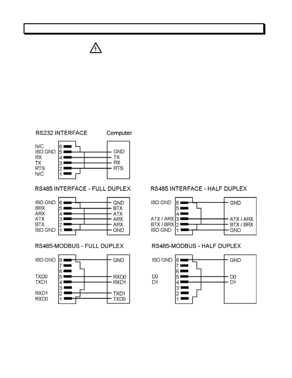
3.2 CONNECTION OF METERS, COUNTERS & TIMERS TO COMPUTER
4