FUTEK IPM500 (D500) Digital Display User Manual
Page 14
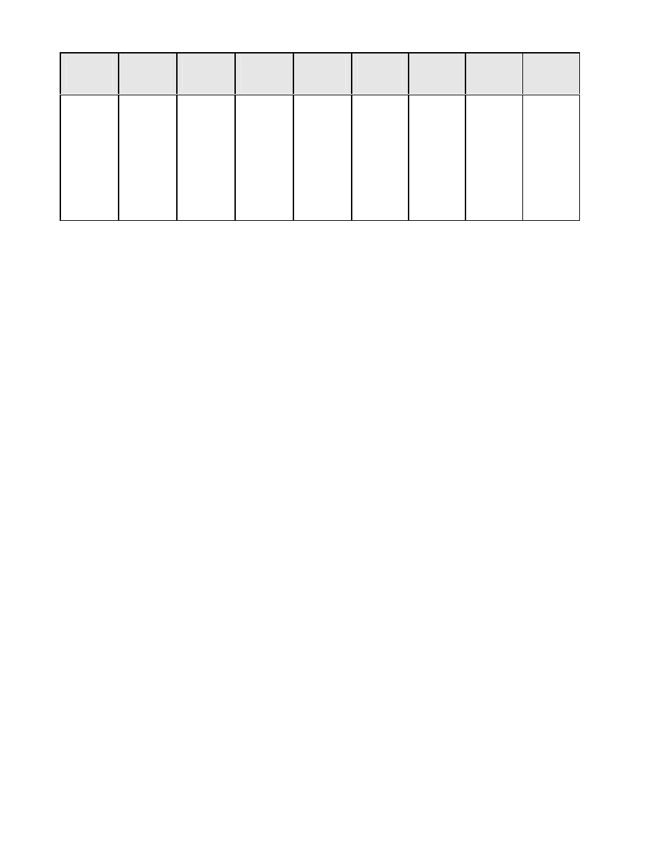
Baud
Rate
Time
1 Item
Min
Gate
Time
2 Items
Min
Gate
Time
3 Items
Min
Gate
Time
4 Items
Min
Gate
300
600
1200
2400
4800
9600
19200
.37s
.18s
.09s
.05s
.02s
.01s
.01s
.34s
.15s
.06s
.02s
.01s
.01s
.01s
.70s
.35s
.18s
.09s
.04s
.02s
.01s
.67s
.32s
.15s
.06s
.01s
.01s
.01s
1.03s
.52s
.26s
.13s
.07s
.03s
.02
1.00s
.49s
.23s
.10s
.04s
.01s
.01s
1.37s
.68s
.34s
.17s
.09s
.04s
.01s
1.34s
.65s
.31s
.14s
.06s
.01s
.01s
The data transmission rate may be reduced by sending data every other reading, every fourth
reading, or less. This selection is made in Ser 1. A computer, if busy with other tasks, may be
unable to keep up with the faster data rates of the meter, so a handshake function is available
that provides the computer with control over the meters data transmissions.
7.3 RTS CONTROL
RTS control does not apply to
RS485. DPMs and counter / timers have two RS232 RTS modes:
unlatched and latched.
In the unlatched mode, the measurement transmission is enabled by a high RTS level and is
disabled by a low RTS level. When disabled, any character being sent is completed. When
enabled, any characters remaining in the data format are transmitted before the next measu-
rement transmission. The computer, when its receive buffer is nearly full, takes the RTS line
low to halt data transmission. When its receive buffer has emptied, it takes the RTS line high to
enable more data transmissions. Some measurements could be missed in the process. The
latched and unlatched modes are selected in "config" "digit 2" in the DPM and by Ser 3 in the
Counter and Scale Meter.
In the latched mode, the RTS input is polled every 3.3 ms. When a high level is detected, RTS
is latched true, even though the RTS line goes low immediately. At the end of each calculation,
the latched RTS value is checked. If it is true, a complete measurement transmission (from 1 to
4 values) is made without interruption, regardless of the state of the RTS line during that time.
At the end of the complete transmission, the latched RTS value is reset false, even though the
RTS line may be high at that instant. The RTS latch does not go true again until the RTS line is
first returned to a low level after the completion of the transmission and then is taken high
again. Latched control provides print command operation by sending a transmission for each
RTS pulse. If a second pulse occurs during the transmission, it is not recognized.
7.3 XON / XOFF CONTROL
Applicable to RS232, not RS485. A measurement transmission is enabled by the receipt of an
ASCII XON character. It is disabled by the receipt of an ASCII XOFF character.
8. COMMAND MODE
8.1 OVERVIEW
In the Command Mode, the device does not send any data automatically, but responds to com-
mands received from a host computer. These commands can be:
� To transmit the latest or peak measurement
� To reset the meter completely or just the peak value and/or latched alarms
� To display a value sent from the computer
� To transmit present setup parameters
� To receive new setup parameters,
� To monitor or alter data in selected memory locations of the meter.
The selection of either the Continuous mode or the Command Mode can be made from the
front panel Menu selection Ser 2. The meter will not respond to a command in the Conti-
nuous Mode, except the command A1, which puts the meter into the Command Mode.
8.2 COMMAND MODE FORMAT
The minimum format is 4 characters. Example: *5A1
After any command that causes a Meter Reset, such as C0, F, W, X, the Counter sends an R
character after the Reset is complete and the Counter is ready to accept a new command.
CHAR 1 - COMMAND IDENTIFIER
All commands begin with * followed by the meter address, then a command letter followed
by a sub-command number or letter. Additional characters may be appended. All commands
terminate with
character via the RS232 / 485 serial port, but will still recognize the *.
Char #
Character
Description
1
2
3
4
*
0-V
A-Z
0-U
Command Identifier (Recognition Character)
Device Address (0 addresses all devices, 1-V specific)
Command Function
Sub-command (or # Bytes or Words of data being transferred)
CHAR 2 - ADDRESS CODES
The next table is the Serial Communication Address Codes following the * for each meter
address number. Also shown is the corresponding character that is set in menu item SER 2.
14