Dwyer ULSS User Manual
Page 6
6 of 30
MN890570
Rev A
COMPONENTS
Step Five
Series ULS is offered in different models. Depending on the model purchased, you may or may not have been
shipped all the components shown below. You do however, need a Series ULS, USB Fob and FKM gasket to
configure, install and operate Series ULS.
FKM Gasket
o
ULS‐ACC‐SGK – used with ULSS series
o
ULS‐ACC‐MGK – used with ULSM series
o
ULS‐ACC‐LGK – used with ULSL series
USB Fob
o
Part# ULS‐ACC‐USB
Quick Start Guide
*Outputs
1. 4‐20 mA, loop powered output
2. 4 SPST 60 VA relays
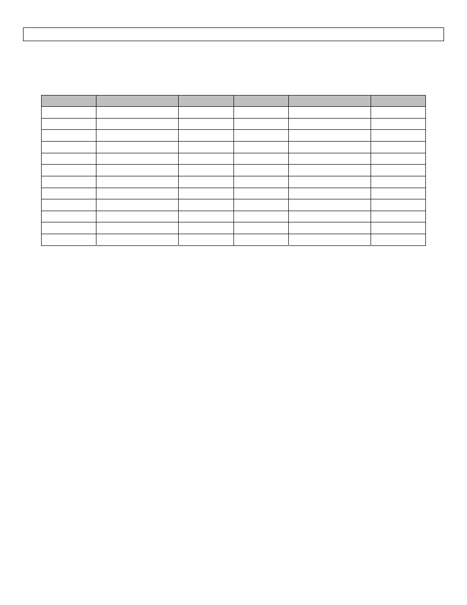
P/N
Max. Range
Dead Band
Thread
Fob
* Outputs
ULSS‐10
4.1’ (1.25 m)
2” (5cm)
1” NPT
No Fob
1,2
ULSS‐11
4.1’ (1.25 m)
2” (5cm)
1” NPT
Fob Included
1,2
ULSS‐20
4.1’ (1.25 m)
2” (5cm)
1” G
No Fob
1,2
ULSS‐21
4.1’ (1.25 m)
2” (5cm)
1” G
Fob Included
1,2
ULSM‐10
9.8’ (3.0 m)
4” (10cm)
1” NPT
No Fob
1,2
ULSM‐11
9.8’ (3.0 m)
4” (10cm)
1” NPT
Fob Included
1,2
ULSM‐20
9.8’ (3.0 m)
4” (10cm)
1” G
No Fob
1,2
ULSM‐21
9.8’ (3.0 m)
4” (10cm)
1” G
Fob Included
1,2
ULSL‐10
18.0’ (5.5 m)
8” (20cm)
2” NPT
No Fob
1,2
ULSL‐11
18.0’ (5.5 m)
8” (20cm)
2” NPT
Fob Included
1,2
ULSL‐20
18.0’ (5.5 m)
8” (20cm)
2” G
No Fob
1,2
ULSL‐21
18.0’ (5.5 m)
8” (20cm)
2” G
Fob Included
1,2