Dwyer ULSS User Manual
Page 17
Rev 5
MN890570
17 of 30
ULSX‐CAL ‐ WRITE TO UNIT
Step Seven
After you have entered configurations and tank
values, click “Write to Unit” and send the
configuration to your Series ULS. Now use ULSX‐CAL’s
file management features to save your configuration
by clicking “Save Config File” and print your wiring
diagram by clicking “Wiring Diagram.”
Write to Unit
Wiring diagram
Save Config File
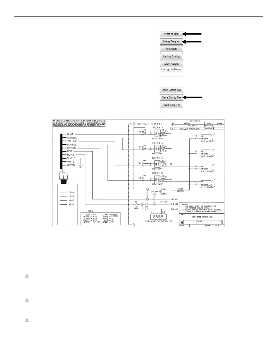
Wiring Diagram ‐ Sample
Diagram will change based upon the configuration of the Series ULS,
use ULSX‐CAL to view appropriate wiring diagram.
Wiring Series ULS: Once Series ULS has been installed, follow the Wiring Diagram provided by the ULSX‐CAL
software. A typical wiring diagram is shown above. Dwyer Instruments, Inc recommends using a qualified
licensed electrician to wire Series ULS and your application’s components.
Configure your Series ULS with ULSX‐CAL and use the wiring diagram button to view the appropriate
diagram. Each configuration will have its own unique diagram. The diagram above is only a sample
and should not be used as a wiring diagram.
Always use stepper relays between the sensor and external loads. For DC circuits use a catch diode
such as 1N4148, shown on the wiring diagram shown above and supplied by ULSX‐CAL.
Once Series ULS is configured, isolate the white and green wires from active power to prevent a
short of the configuration circuit.