Dwyer ULSS User Manual
Page 18
18 of 30
MN890570
Rev A
WIRING
Step Eight
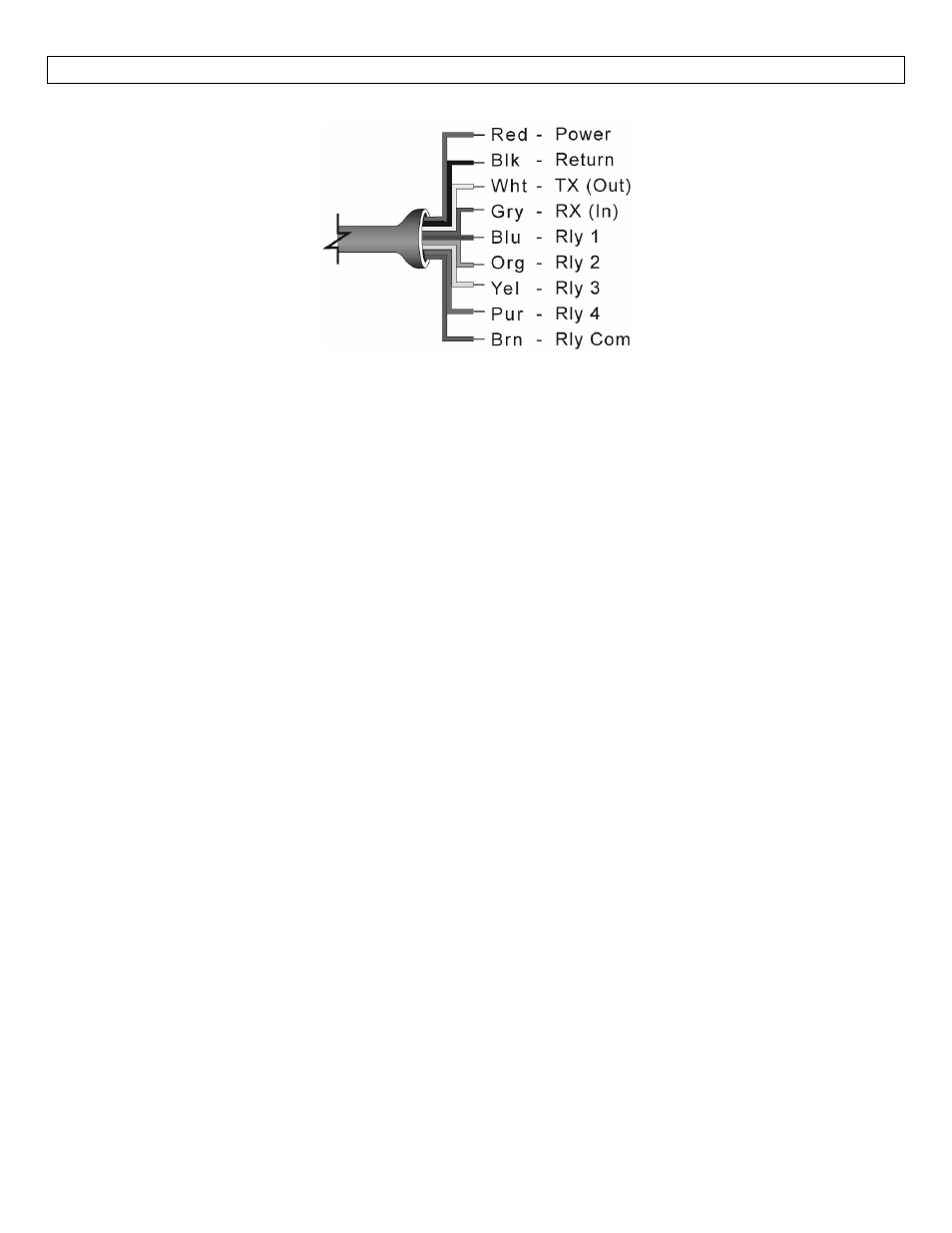
Wire Connections:
Red & Black: Red and Black leads are for connection to a 12‐28 VDC power supply or to a 4‐20 mA loop power
source (Series ULSS, ULSM & ULSL only). The red and black wires can be extended up to 1,000 feet using a 22
gauge or larger wire, however do not extend the green and white wires.
White & Green: White and Green leads are reserved for use with ULSX‐CAL and should not be connected
during usage in the application. These wires should not be connected to ULSX‐CAL while power is supplied
from any source other than the ULS‐ACC‐USB Fob. The maximum cable distance between the computer and
Series ULS is 15’.
Never allow the white or green wires to touch any power supply.
Blue, Orange, Yellow, Purple & Brown: Blue, Orange, Yellow & Purple wires are the relay contacts (normally
open) from each of the relays respectively. The Brown wire is the common for all the relays. Relay selection is
determined by the configuration in ULSX‐CAL. Note: Series ULS uses latching relays. When power is removed to
the sensor, the relays will remain in their last state. Ex: If the relay is energized, when power is removed, the
relay will remain in an energized state.
General notes for electrical connections, usage and safety:
Where personal safety or significant property damage can occur due to a spill, the installation must
have a redundant backup safety system installed.
Wiring should always be completed by a licensed electrician.
Supply voltage should never exceed 28 VDC.
Always use stepper relays between the sensor and external loads. For DC circuits use a catch diode
such as 1N4148, shown on previous page.
Protect the sensor from excessive electrical spikes by isolating the power, whenever possible.
The sensor materials must be chemically compatible with the liquids to be measured.
Design a fail‐safe system for possible sensor and/or power failure.
Never use the sensor in environments classified as Hazardous.