Dwyer ULSS User Manual
Page 21
Rev 5
MN890570
21 of 30
INSTALLATION
Step Nine
Fitting Selection: Check the part number to determine the required fitting mount size and thread type. Series
ULS is commonly installed in tank adapters, flanges, brackets or standpipes. Note: Always include the gasket
when installing the Series ULS.
1. Tank Adapter: Select a tank adapter fitting, such as the ULS‐ACC‐410 for the Series ULSS & ULSM or
the ULS‐ACC‐420 for the Series ULSL.
a. For best results, select a 2” tank adapter and add a reducer bushing such as the ULS‐ACC‐121,
thread x thread, reducer bushing.
b. Avoid tank adapter (thread x thread) styles and/or pipe stops forward of the installed
transducer.
c. Always mount the tank adapter so the majority of fitting is outside the tank.
i. Never mount the tank adapter upside down or the bulk of the material is inside the
tank.
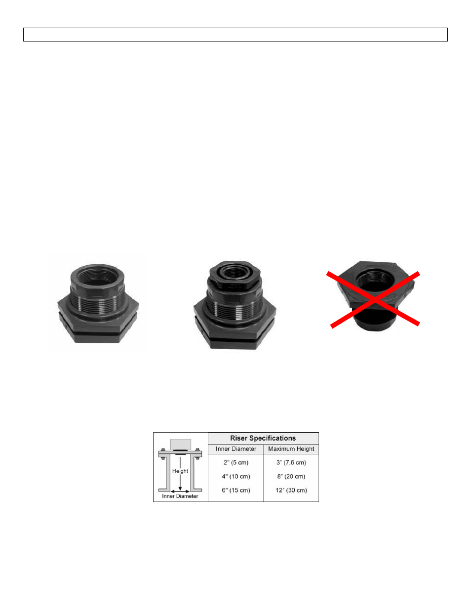
2” Tank Adapter
Socket x Thread
(ULS‐ACC‐420)
Tank Adapter (ULS‐ACC‐420)
w/ 2”x 1” Reducer Bushing
(ULS‐ACC‐121)
Tank Adapter
Thread x Thread
Do not use thread x thread
2. Riser: Installations with tall, narrow risers can impede the acoustic signal.
a. Series ULSL: 2” (5 cm) diameter risers should be no taller than 4” (10 cm). Larger diameter
risers should be no taller than 12” (30.5 cm).
b. Series ULSS & ULSM:
Note: Do not exceed the dimensions listed above