Dwyer ULSS User Manual
Page 19
Rev 5
MN890570
19 of 30
WIRING
Step Eight
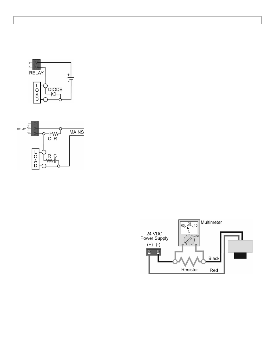
Switching Inductive Loads: The use of suppressors (snubbers) is strongly recommended when switching
inductive loads to prevent disrupting the microprocessor’s operation. The suppressors also prolong the life of
the relay contacts. Suppression can be obtained with a catch diode for DC circuits and a resistor‐capacitor (RC)
for AC circuits.
Catch Diode
Always use stepper relays between the sensor and external loads.
For DC circuits use a catch diode such as 1N4148, shown on left.
Refer to the following circuits for RC network assembly and installation:
Choose R and C as follows:
R: 0.5 to 1 Ohms for each volt across the contacts
C: 0.5 to 1 μF for each amp through closed contacts
Notes:
1. Use capacitors rated for 250 VAC.
2. RC networks may affect load release time of solenoid loads. Check
to confirm proper operation.
3. Install the RC network at the meters relay screw terminals. An RC
network may also be installed across the load. Experiment for best
results.
Voltage Output: Series ULS can be used as a 0 to 5 or 0 to 10 VDC output device. A resistor will need to be
added to the circuit to enable a voltage output (refer to the wiring diagram below).
0‐5 VDC output
o
Add a 250 Ohm resistor
o
Actual output will be 0.8 to 5 VDC
0‐10 VDC output
o
Add a 500 Ohm resistor
o
Actual output will be 2 to 10 VDC
When using ULSX‐CAL, under Number of Pumps, select 4‐20 mA Transmitter Only to simplify the configuration
in ULSX‐CAL.