Caleffi 6000 User Manual
Page 33
8
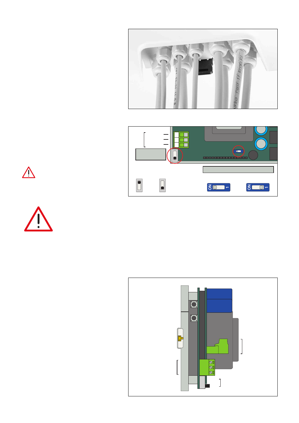
Description of internal buttons and terminals
On the connection base there are two buttons,
which can be actuated by opening the front of the
appliance: a reset button and a button for disabling
the keypad (PIN).
Enabling functions-Jumper and microswitch
settings
Inside the appliance there are two switches:
One is used to enable/disable the Thermal Shock
function.
The other is used to connect the internal battery
(this is done at the time of installation).
Caution: If the battery is not activated
the battery alarm will be displayed.
PIN
disable
Reset
PIN code
disabling button
Appliance
reset button
Screw to
close the frontal
panel with hole
for lead-sealing
Temperature
probe terminal
RS485
interface
terminal
Microswitch for
enabling thermal
shock function
2
1
2
0
1
9
O
N
1
Flow
Common
Return
Shock
enabled
Shock
disabled
(factory setting)
M
Battery connected
Battery disconnected
Temperature
pr
obes
Battery connection
Thermal
shock
activation
Location of cable fairleads
When making the electrical connections, keep to
the following sequence for wiring the terminal strip
and tightening the cable fairleads:
1 Electric supply*
2 Mixing valve actuator*
3 Flow probe*
4 Recirculation probe*
5 RS485
6 Relay 3
7 Relay 1
8 Relay 4
9 Relay 2
*Already factory assembled
1
3
4
5
6
7
9
8
2
CAUTION!
The regulator is configured so that it executes a daily ball movement cycle, to ensure
efficient ball operation and cleaning. This procedure is carried out after the disinfection
program, if active, or anyway after 24 hours have elapsed if disinfection is not active. This
function can be deactivated in the “SETTINGS” menu through the ANTI-CLOG item by
entering the release code 5566 and confirming with ON-OFF.
Eliminating this function increases the risk of deposits forming on moving parts of the valve.
If the disinfection function should be eliminated as well, it is advisable to proceed in the following order: first
eliminate the ANTI-CLOG function, then eliminate the disinfection function.