Figure 44 four repeater data bus, Figure 45 wire length vs. data speed – Detcon 1600A-N1R User Manual
Page 38
1600A-N1R
1600A-N1R Instruction Manual
Rev. 0.1
Page 34 of 38
In this case it is impossible to balance the data bus because there is no distinct beginning or end to the cable
run. The best way to make this type of installation successful is to install repeaters in a few key areas as
shown in Figure 44. Repeaters are used to eliminate the t-taps or stubs, which can cause communication
problems. The location and number of stubs will dictate where repeaters need to be installed. Four repeaters
are installed to eliminate the stubs.
C
%QPVTQN4QQO
D
4V
4V
4V
4V
4V
4V
4V
4V
4V
4V
TGRGCVGT
TGRGCVGT
TGRGCVGT
TGRGCVGT
Figure 44 Four repeater Data Bus
Notice there are 5 different data buses that make up the communications network. The first one consists of the
master located in the control room, device 09, repeater #1, device 01, device 02, repeater #2, device 03, and
device 05. Notice the termination resistors at the beginning and end of this bus section. The second bus starts
at repeater #2. It consists of the repeater and device 04. Since this is a new bus, it has terminating resistors at
each end. The third bus starts at repeater #1. It includes device 08, repeater #3, device 07, repeater #4, and
device 06. It also has its own resistors. The fourth bus starts at repeater #3 and consists of the repeater, device
0A, and the terminating resistors. The fifth bus starts at repeater #4 and consists of the repeater, device 0B,
and termination resistors. This configuration isolates all of the t-tap stubs. This configuration should function
properly as long as the wire type and proper distances are observed.
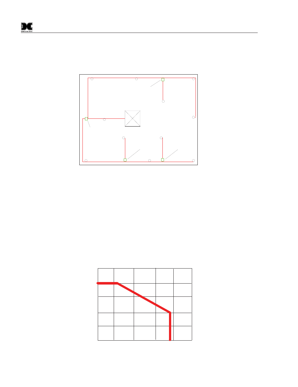
The following chart shows an approximation of wire length vs. data speed. Detcon operates its equipment at
19,200bps (baud) and lower.
Figure 45 wire length vs. data speed
ODRU
ODRU
ODRU
MDRU
MDRU
MDRU
HV
HV
HV
HV
HV
HV