Device hook-up, Figure 42 daisy chain wiring diagram, Figure 43 unbalanced data bus – Detcon 1600A-N1R User Manual
Page 37
1600A-N1R
1600A-N1R Instruction Manual
Rev. 0.1
Page 33 of 38
Device Hook-Up
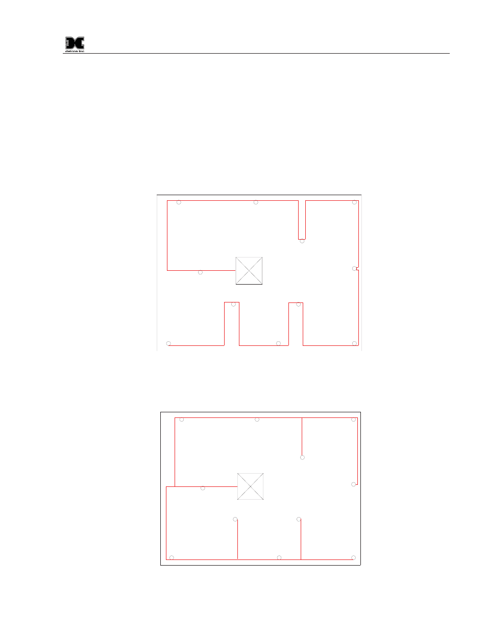
Installation should begin by deciding where devices will be located and how the connections between devices
and the master will be established. The ideal scenario would look like Figure 42. The example shows the 880
Controller connected to 11 slave devices using a daisy-chain wiring scheme. This would require 2 different
twisted pair cables, one pair for power, and the other for the RS-485 data bus.
Connections would be point-to-point starting at the master and running to the last slave. The RS-485 data
cable should come into the sensor enclosure and be connected to the A & B terminals. The next segment of
cable should also connect to the A & B terminals and leave the enclosure headed for the next device. The
shields must be tied together inside the enclosure and not allowed to short to any other wires or surfaces. The
shield should be connected only inside the Model 880 cabinets to the shield terminal. The Rt label in the
drawing shows where the termination resistors would be installed.
Figure 42 Daisy Chain wiring diagram
C
%QPVTQN4QQO
D
4V
4V
Daisy Chain Wiring is ideal, although wiring may already exist or the wiring cannot be run this way for some
reason. Figure 43 shows a more realistic wiring situation that may occur.
Figure 43 Unbalanced Data Bus
C
D
%QPVTQN4QQO