Detcon 1600A-N1R User Manual
Page 10
1600A-N1R
1600A-N1R Instruction Manual
Rev. 0.1
Page 6 of 38
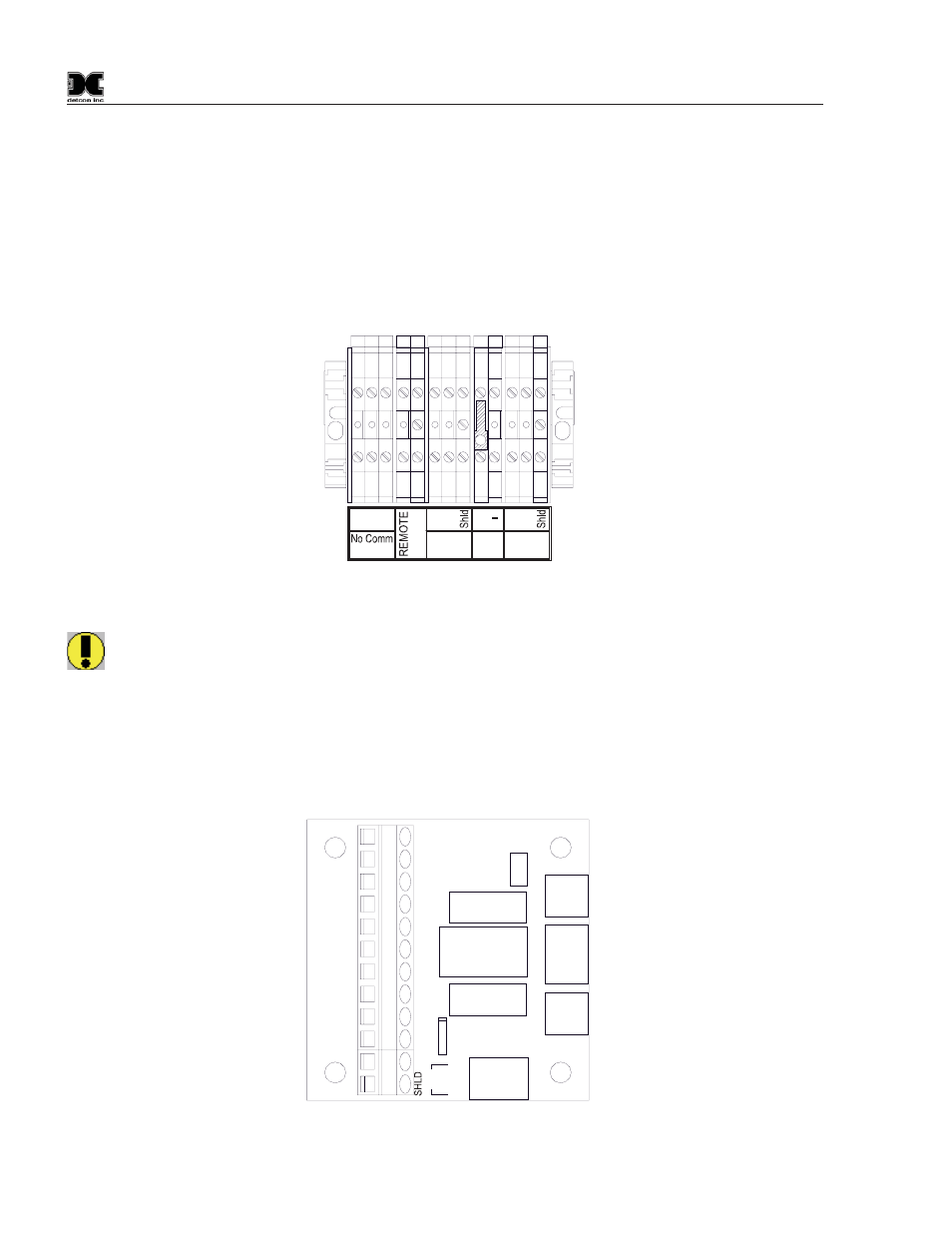
Connect the RS-485 wiring from remotely located I/O devices to the terminals located on the Back Panel.
These terminals are labeled RS-485 “A” (+), “B” (–), and “Shld” (shield) for primary RS-485 communication
(Figure 6). RS-485 wiring should consist of a two conductor, shielded twisted pair (Belden cable P/N 9841 is
recommended). Also available are two output terminal blocks to provide 24VDC to external RS-485 devices.
This power should be used only to power remotely located I/O modules and/or sensors, and should not exceed
a total of 3 Amps accumulative for all I/O modules and sensors attached to the controller. (I.E. if there are two
modules mounted on the enclosure that have an accumulative current draw of 0.5Amps, the sensors and/or I/O
modules connected to the output 24VDC should not exceed 3.0Amps.) Refer to each module and sensor
manual for maximum expected current draw from each device.
C
NO
NC
A
B
+
RS-485 VDC
A
B
RS-485
Primary
Second
Out
RESET
Figure 6 Interface wiring Terminals
WARNING: Do not attach more devices to the controller power supply than the power supply has the
capacity for, as damage may occur to the controller and will void the warranty. Modules and sensors
attached to the unit that exceed this 3Amp power rating should be powered by an external power
supply capable of handling the extended load.
The secondary serial RS-485 port from the controller is connected to a set of Terminal Blocks on the DIN Rail
(Figure 6). The Terminal Blocks are labeled Secondary “A, B & Shld” and can be connected to a PLC,
PC/HMI, DCS, or other Modbus™ master polling serial communications device, refer to Secondary
Modbus™ Port Section 5.5.
J1
J2
J3
J4
J5
U1
U2
1
3
4
5
6
7
8
9
10
12
11
2
K1
XPSN
PWR
XPSN
GND
SCRN
PWR
SCRN
GND
PLC
PWR
PLC
GND
NO
COM
FLT
RST
A
B
+
-
NC
NO
C
+
-
A
B
SHLD
FLT
/C
O
MM
RESET
PO
WER
RS-485
Figure 7 Interface PCA