Detcon 1600A-N1R User Manual
Page 19
1600A-N1R
1600A-N1R Instruction Manual
Rev. 0.1
Page 15 of 38
The second Model DA4 module with identification switches set to 05 and handling sensor inputs 5 – 8, would
appear as follows:
CH #
DA4 Address
05 thru 08
05 Hex
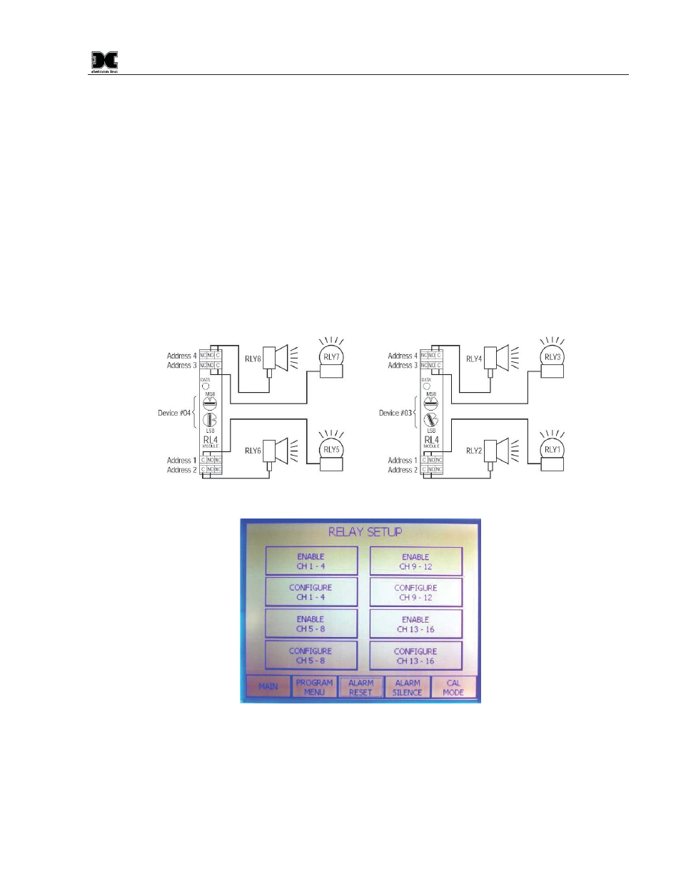
4.1.3 Relay Activation and Configuration.
For the Relay Output set-up, follow the same logic as with the gas channel set-up. Press the enable
“ENABLE” key for the CH1-4 box to use the first RL4 module and then set its Device# to 41. Note, the block
now shows as “ENABLED”. The second part of Relay Setup requires the decision of how the individual relay
contacts will be configured. Press the block labeled “CONFIGURE CH 1-4”, and a relay setup screen will
appear. Each relay must be selected as latching or non-latching, energized or non-energized, and silenceable
or non-silenceable. These selections are shown in three small blocks to the right of the Relay # input. Make
selections by pressing the buttons on screen (Figure 22). Entries are saved automatically when exiting the
screen by pressing MAIN or Device Setup. Continue this sequence for all other relays.
Figure 20 Addressing Relay Modules
Figure 21 Activating Relay Outputs