3 initial power checks, 4 setting device identification on the i/o modules – Detcon 1600A-N1R User Manual
Page 14
1600A-N1R
1600A-N1R Instruction Manual
Rev. 0.1
Page 10 of 38
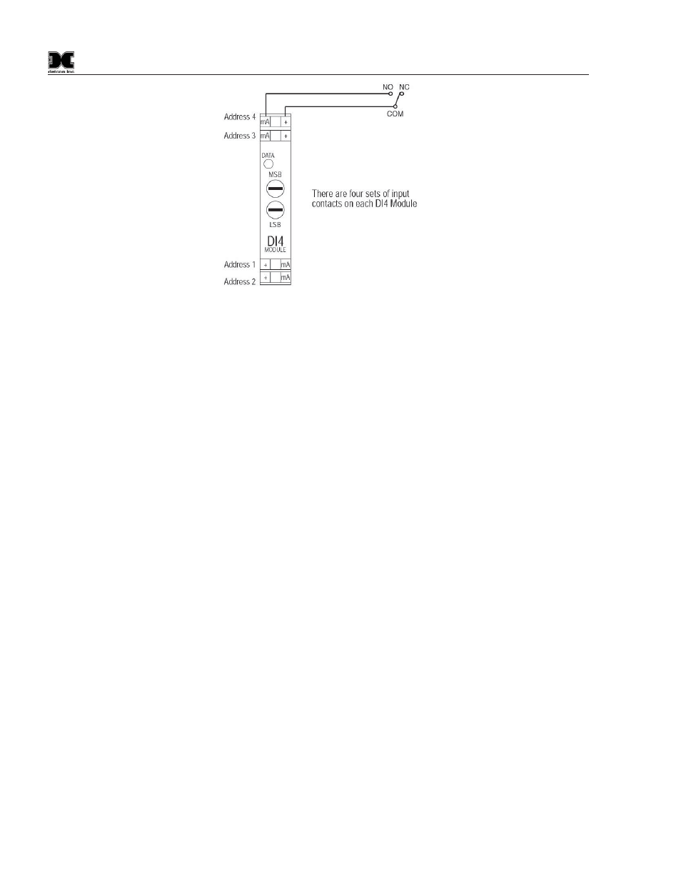
Figure 13 Model DI-4 Module
General Wiring Notes:
When I/O Modules are located at a remote distance from the controller, an end-of-line terminating resistor
is required to enhance communications reliability. Identify the last I/O Module in the loop, and open the
module casing using the clip release points. Locate and install the jumper on JP6 (TERM). This adds a
120
: resistor to the end of the line. If applicable, add a 120: resistor to the last Modbus™ gas sensor.
Follow generally accepted guidelines for RS-485 serial networks. Do not wire I/O Modules and/or
Modbus™ gas sensors in long-distance ‘T-Tap’ configurations. Stay with direct serial configurations. See
Appendix A for serial communications configuration guidelines.
Use Detcon Recommended cabling whenever possible.
x Belden P/N 1502P cable is recommended for a single cable providing serial communications and
power.
x Belden 9841 cable is recommended for a single cable providing serial communications only.
Ground the cable shielding at the Model 1600A-N1R Controller only. Other points of grounding may
cause a ground loop, and induce unwanted noise on the RS-485 line, which in turn may disrupt
communications.
3.3 Initial Power Checks
Before applying power, make sure that all I/O Modules are correctly installed and that all wiring connections
between I/O modules and external devices are made correctly.
NOTE: Applying power with devices hooked up incorrectly may cause damage.
Turn the applicable AC and DC Breaker Switches to the ON positions. Verify that the main touch-screen
LCD comes on displaying gas readings. After 5 seconds, verify that all the I/O modules are being polled by
observing a sequence of blinking LED’s on the I/O Modules representing successful serial communication.
NOTE: The polling of the input devices takes place more frequently than the communications to the relay
output devices. The sequence of polling communication will follow the order of the I/O device switch
addresses.
3.4 Setting Device Identification on the I/O Modules
NOTE: If the Model 1600A controller has been configured at Detcon, you may elect to skip to the
Operator Interface (Section 4.0) for further review of system operation.