Detcon 1600A-N1R User Manual
Page 20
1600A-N1R
1600A-N1R Instruction Manual
Rev. 0.1
Page 16 of 38
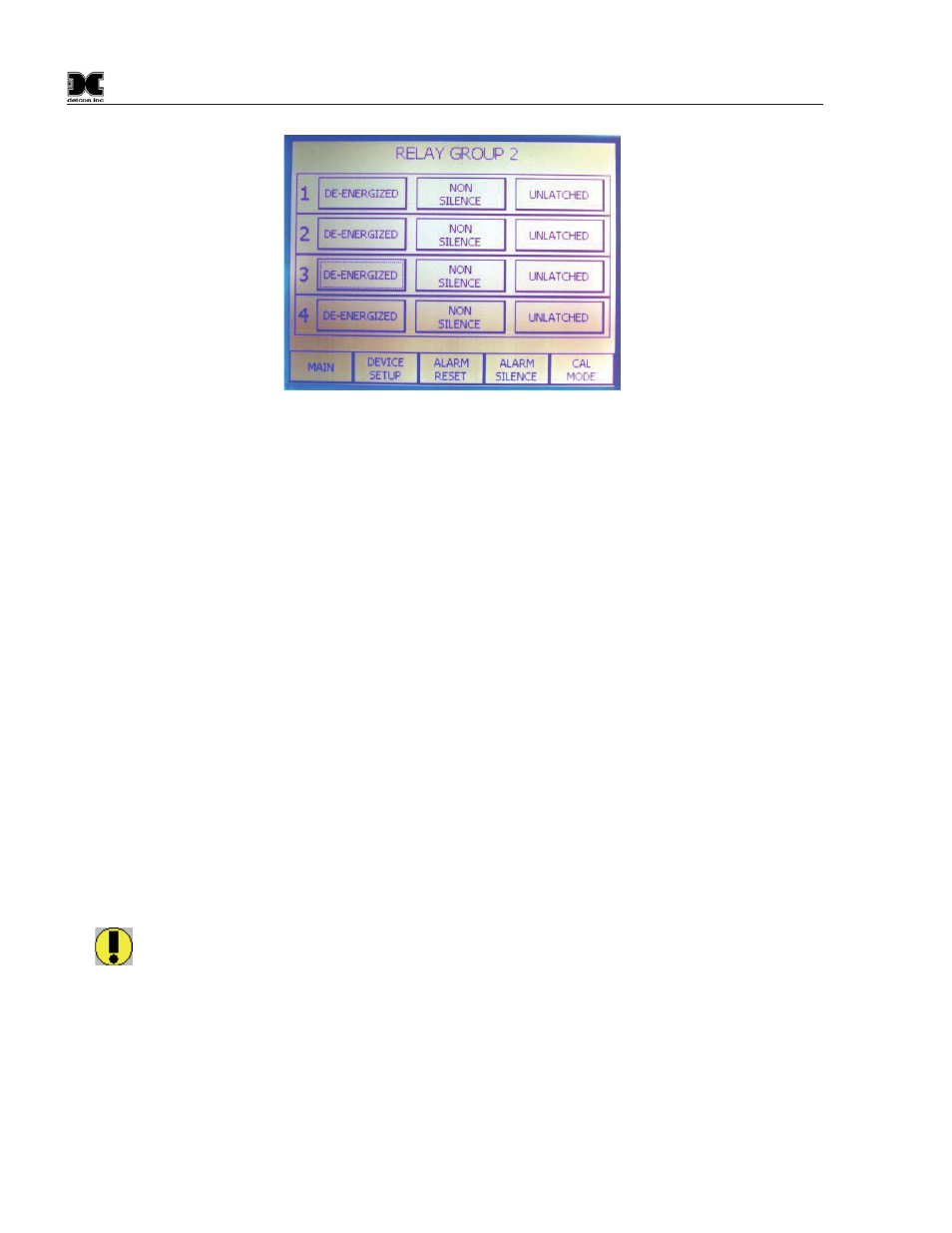
Figure 22 Setting up Relay Outputs
NOTE: This selection controls the output state for that relay regardless of how many alarm/fault
conditions for which the relay output may be used. A single relay output can only be set up in one
configuration.
The set-up for the first Model RL4 module would look like this:
Relay
#
RL4
Address
01 thru 04
41 Hex
The second Model RL4 module set to 69 (45Hex) and handling relays 5 – 8, would appear as follows:
Relay #
RL4 Address
05 thru 08
45 Hex
4.1.4 Serial Inputs
Activating Serial Inputs
The 1600A can handle 16 serial inputs from either a model 600 or model 700 series sensor. To activate the
serial inputs enter Program Mode. Touch the Serial Sensors button to read “Serial Sensors 700 Series” or
toggle to “Serial Sensors 600 Series”. This is a global command and as such all sensors must be either 600 or
700 series. See Figure 23 touch the Serial button and select each channel that is to be enabled or disabled,
Figure 24
WARNING: If the wrong 600/700 selection is made while sensors are connected, The Modbus
may need to be reset to re-initialize Modbus communications. Refer to the “Modbus Reset”
function in the SCREEN UTILITIES menu to re-start Modbus™ polling (Section 5.3).