1 installing the i/o modules, Figure 8 i/o module installation, I/o connector rs-485 cable – Detcon 1600A-N1R User Manual
Page 11: Rs-485 and power cable
1600A-N1R
1600A-N1R Instruction Manual
Rev. 0.1
Page 7 of 38
The No Communications Fault Relay is connected to a set of Terminal Blocks on the DIN Rail (Figure 7 and
Figure 5.) The Terminal Blocks are labeled “NO COMM” “C”, “NO” and “NC”. The Interface PCA,
mounted on the back of the Display Panel, will de-energize the No Comm/Fault relay in the event there is a
Communication Fault with any activated device. A ‘No Communication Fault’ condition will create a ‘short’
between the ‘Common’ and ‘Normally Closed’ contacts, and create an open between the ‘Normally Open’ and
‘Common’ relay contacts. This is required for fail-safe operation. There is a two-minute delay before any
active device will trigger a no communication condition.
The unit includes connections for an optional Remote Alarm Reset Switch. A set of Terminal Blocks is
supplied for the connection of a Remote Alarm Reset Switch that can be mounted anywhere outside the unit.
The Remote Alarm Reset incorporates a set of normally closed contacts that cause the unit to reset the Alarms
when contact is broken. To install a Remote Reset Switch the jumper between terminal blocks 8 and 9
(labeled “Remote Reset”) must be removed and the switch wired to these terminals. Connect only a normally
closed switch to these terminal blocks. If more than one switch is to be connected, the switches must be
connected in series.
NOTE: The Remote Alarm Reset switch should be a ‘Normally Closed’ Switch and should be wired as
such. Failure to wire the switch correctly will cause the Enclosure Alarm Reset and all subsequently
connected Remote Alarm Reset Switches to be non operational.
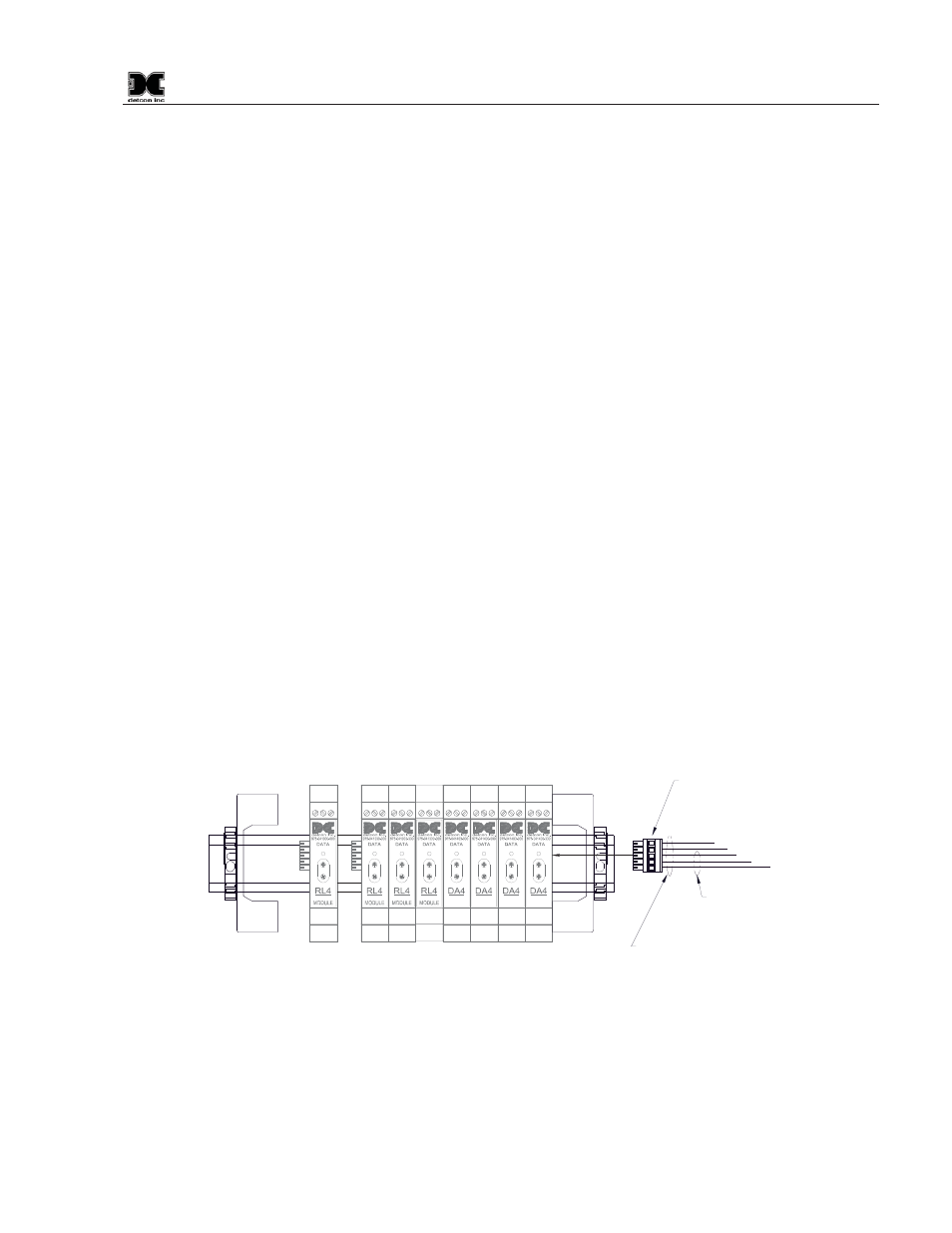
3.1 Installing the I/O Modules
Normally, maximum of one (1) I/O module may be installed on the main NEMA 1 rack. Additional modules
should be mounted in a separate enclosure.
I/O modules are mounted to industry-standard 37.5 x 7.5 mm din-rail. Install the first I/O module on the din
rail and slide it all the way to the right side stop. When installing additional I/O modules, make sure there is
about 0.5 inch clearance spacing on either side of the module and snap onto the din rail (the 0.5” spacing is to
allow for connector clearance). Once the I/O module is snapped onto the din-rail, slide it to the right and
assure that it firmly plugs into the next module. Repeat as necessary for the balance of the modules. The
1600-A Controller Enclosure has room for a maximum of two (2) I/O modules (provided the Modbus™
Spacers are removed). Additional modules should be mounted in a separate enclosure..
RELAY
COMM
M
S
D
L
S
D
4-20mA
INPUT
COMM
M
S
D
L
S
D
4-20mA
INPUT
COMM
M
S
D
L
S
D
4-20mA
INPUT
COMM
M
S
D
L
S
D
4-20mA
INPUT
COMM
M
S
D
L
S
D
RELAY
COMM
M
S
D
L
S
D
RELAY
COMM
M
S
D
L
S
D
RELAY
COMM
M
S
D
L
S
D
SB
A
-
+
S
B
A
-
+
I/O Connector
RS-485 Cable
(Beldon P/N 9841
or equalivant)
RS-485 and Power Cable
(Beldon P/N 1502P or Equalivant)
Figure 8 I/O Module Installation
For addressable I/O modules or Modbus™ sensors that are being located remotely from the Model 1600A-
N1P controller use Belden 1502P cable for serial and power connections. For serial only connections use
Belden 9841 cable.