2 da4 set up – Detcon 1600A-N1R User Manual
Page 18
1600A-N1R
1600A-N1R Instruction Manual
Rev. 0.1
Page 14 of 38
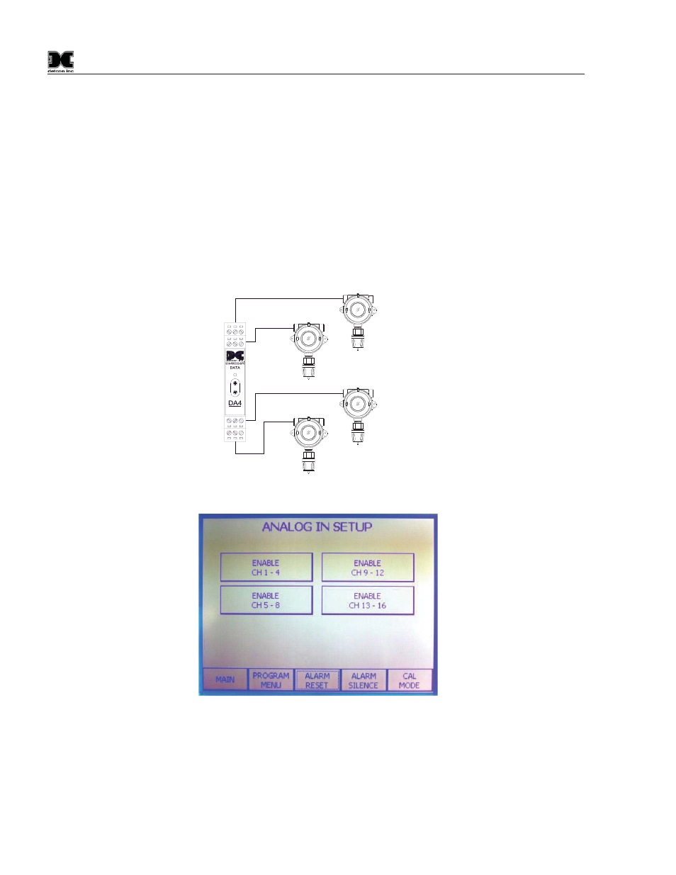
4.1.2 DA4 set up
Touch the Analog Input/DA4 button. This function enables up to 4 DA4 modules. They are identified as CH
1-4, CH 5-8, CH 9-12, and CH13-16. There are four sensor inputs for each DA4 module, labeled 1 – 4. The
address for each module is:
CH 1-4
01 Hex
CH 5-8
05 Hex
CH 9-12
09 Hex
CH 13-16
0D Hex
The DA4 menu is entered by pressing the Analog Input from the Program Menu. Channels 1 thru 4 are in
Module 1-4. Channels 5 thru 8 are in Module 5-8 and so on. Simply press the Module button for each module
you wish to enable. When done press the Program Menu button.
4-20mA
INPUT
COMM
M
S
D
L
S
D
Typical Sensors
Sensor 2
Sensor 1
Sensor 3
Sensor 4
Figure 18 Addressing DA Modules
Figure 19 DA4 / Analog input Activation
Example: The 1600A is to be set up for two Model DA4 input modules. Make sure that the switch setting for
the first Model DA4 module is set to 01, representing the first gas input and is wired to terminal connection #1,
for position 1 on the module’s wiring connector. The first Model DA4 module would look like this:
CH #
DA4 Address
01 thru 04
01 Hex