Figure 14 setting device addresses – Detcon 1600A-N1R User Manual
Page 15
1600A-N1R
1600A-N1R Instruction Manual
Rev. 0.1
Page 11 of 38
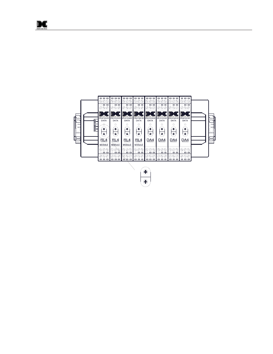
For a unit that has not been properly configured, the I/O modules must be serially addressed to establish
correct communications. Typically, the I/O modules will be identified from 01 to FF starting from the module
on the right hand side of the stack. The I/O module’s identification is established by setting the two rotary
switches to the correspondingly correct position. The top rotary switch sets the most significant bit (MSB).
The bottom rotary switch sets the least significant bit (LSB). For an address of 01, set the top switch to 0 and
the bottom switch to 1. See Appendix B for Decimal to Hexadecimal conversion.
NOTE: All addresses must be unique. There can be no duplication of addresses or a failure to
communicate will occur.
RELAY
COMM
M
S
D
L
S
D
4-20mA
INPUT
COMM
M
S
D
L
S
D
4-20mA
INPUT
COMM
M
S
D
L
S
D
4-20mA
INPUT
COMM
M
S
D
L
S
D
4-20mA
INPUT
COMM
M
S
D
L
S
D
RELAY
COMM
M
S
D
L
S
D
RELAY
COMM
M
S
D
L
S
D
RELAY
COMM
M
S
D
L
S
D
M
S
B
L
S
B
012
3
4
5
678
9A
B
C
D
EF
0
12
3
4
5
678
9A
B
C
D
EF
Figure 14 Setting Device Addresses