Measurements area, Graphics – DeFelsko PosiTector 100 v.4.0 User Manual
Page 11
100 Series
Page 11
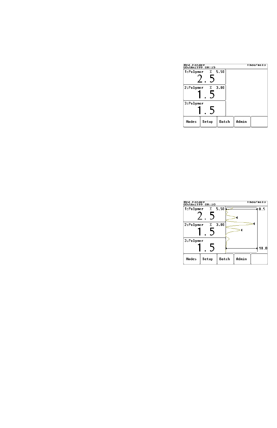
Measurements Area
The left hand side of the screen displays up to five (5) individual coating layers
as set by the
Setup
q
q
Application Setup menu option (pg.19). Each layer
is described in its own box.
The number appearing in the top left of each box is
the layer number. The top box, layer 1, represents the
surface layer. The bottom box represents the layer
closest to the substrate. The coating name appears
beside the layer number.
The large number in the center of each box represents
the thickness of that coating layer in the measurement units shown in the Status
Bar. If GRAPHICS MODE is turned on, this value corresponds to the
appropriate triangle arrow.
The cumulative total of the individual layers is displayed in the top right of each
box as subtotaled from the bottom up. Therefore the
∑
value in the top box
represents the total coating thickness.
Graphics
The right hand side of the screen can be used to
display a graphical representation of the ultrasonic
echo as it passes through the coating system. It is
controlled by the
Modes
q
q
Graphics ON/OFF
menu option.
As the probe switch is depressed and the ultrasonic
pulse travels through the coating system, the pulse
encounters changes in density at the interfaces between coating layers and
between the coating and the substrate.
These interfaces are depicted by a “peak”. The greater the change in density the
higher the peak. The more gradual the change in density, the greater the width of
the peak. For example, two coatings layers made of essentially the same material
and “blended” would result in a low, wide peak. Two materials of very different
density and a well-defined interface would result in a high, narrow peak.
The Model 100 chooses the highest of peaks when trying to determine coating
layer thickness. If the number of layers is set to 3, for example, the 3 highest
peaks between the A & B Gates are selected as the interfaces between these
layers. The peaks that the Gage selected are indicated by black triangle arrows.