2 lodar wireless remote, 1 tractor hook up, 1 labeled lodar remote diagram – Seed Hawk AIRCART 2014 User Manual
Page 14
SEED HAWK
®
2014 AIRCART OPERATOR’S MANUAL
SEED HAWK
®
2014 AIRCART OPERATOR’S MANUAL
20
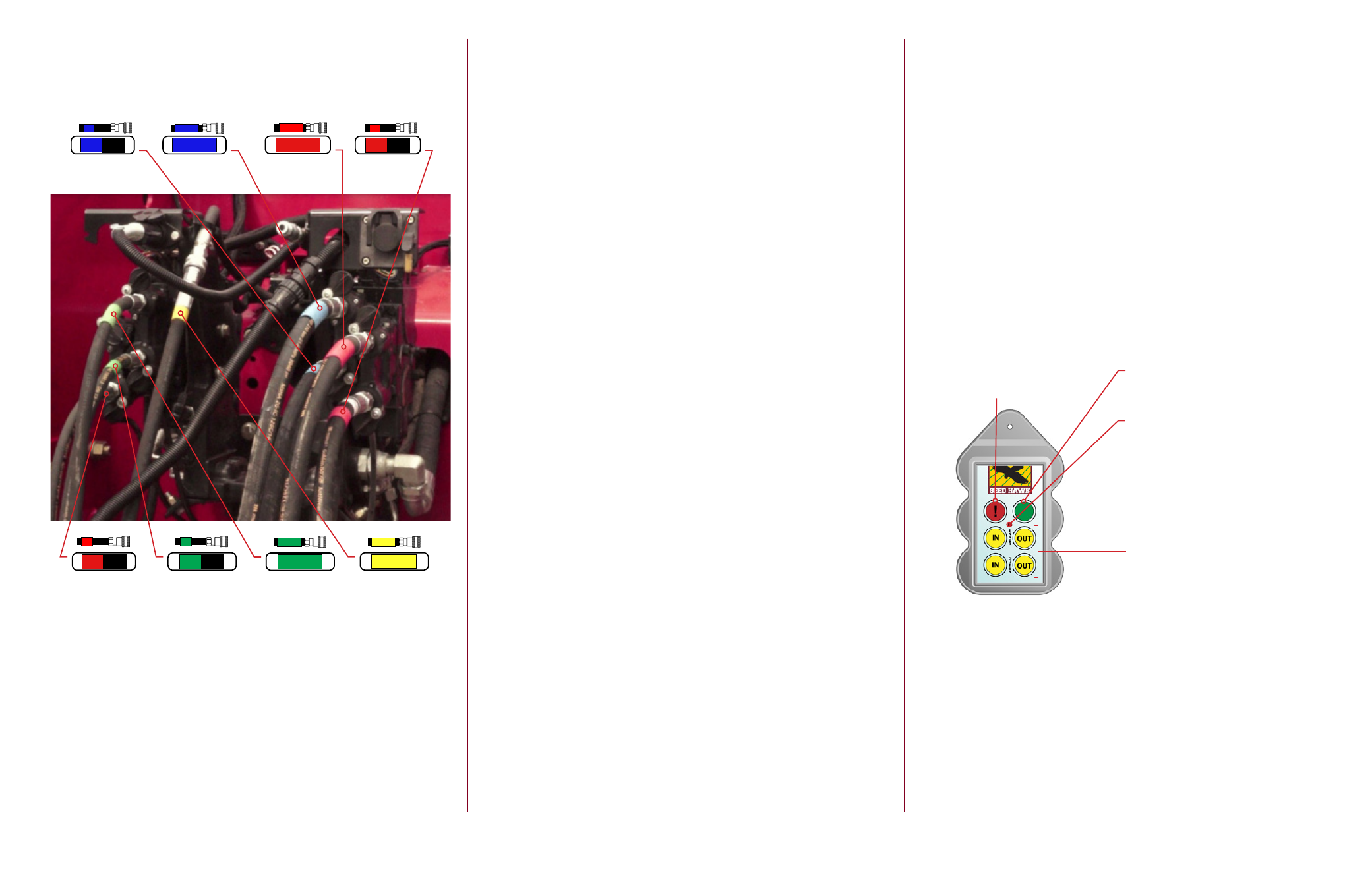
4.1.1 Tractor Hook up
The picture below is for representation only. Hydraulic hose hook up will vary
depending on tractor and Toolbar configuration.
Opener
Up
Fan 1
Pressure
Wing
Up
Wing
Down
Fan 2
Pressure
Toolbar
Dump
Fan 1
Return
Fan 2
Return
21
You must also connect the case drain lines (two ½” hoses, one with a yellow
band) to return hydraulic fluid back to the tractor reservoir. One case drain
line is a ½” (13mm) line from the fan. The other case drain line is a ½” (13mm)
line from the hydraulic manifold. The case drain line(s) MUST return to the
tractor UNRESTRICTED. Failure to do so can cause damage to the hydraulic
cylinders or fan motor and will void manufacturer’s warranty.
4.1.2 Case Drain Lines
4.1.3 Tractor Hydraulic Requirements
Fan Circuit(s) (continuous when seeding):
9-13 gal/min (35-50 L/min) Single Fan
18-24 gal/min (68-90 L/min) Dual Fan
4.2 Lodar Wireless Remote
4.2.1 Labeled Lodar Remote Diagram
The
Stop Button switches off the
receiver and keypad functions
The
Reset Button activates the re-
ceiver and keypad function buttons
Function Buttons
Auger Remote
The
LED Blinks when transmitter
and receiver are active. The
LED’s
ON when a transmitter button is
pressed.
NOTE: As a safety feature,
the Transmitter automatically
transmits a STOP signal after
30 minutes; this deactivates
the Receiver and the Trans-
mitter keypad