Farm manager 16 stage scs™ with back-up – Hired-Hand Farm Hand Series: SCS w/Back-Up User Manual
Page 6
Part No. 4801-5117 Rev. 8-01
Farm Hand SCS
4
AUTO
OFF
ON
Stage Control Switch (3 position)
Stage Status Indicators
Write in
the Name
you
choose for
this Stage
Stage Control
Switches
Main
Display
Control
Buttons
Back-Up
Stage
Indicators
Display
Indicators
Farm Manager 16 stage SCS™
with Back-Up
5.1
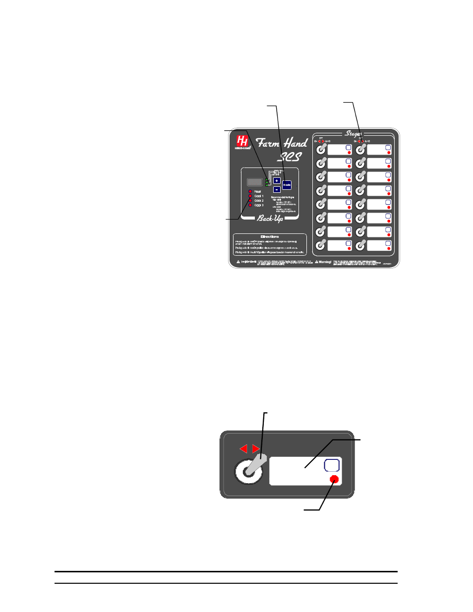
Illustration Of Farm Hand SCS™ with Back-Up
The Farm Hand SCS™ with Back-Up is designed to operate as a one room controller. (See Section
7.) There are two main areas on the SCS faceplate. These are the Stage Switch area and the Main
display area. The Stage switch area contains the stage control switches and an area to label the
function of an individual stage. The label area also contains the stage status indicator. See Section
5.2 for a more detailed
discussion of this area.
The Main display area
contains controls and
indicators for
monitoring and
programming the SCS
Back-Up. When the
controller is operating
normally, the Main
Display shows the
current room
temperature. The
display can also display
the high and low room
temperature limits. See
Section 12.1. The
Control buttons are
Mode, plus (+), and
minus (-) and are used
to select the
information in the main
display. The type of information in the main Display is indicated by which Display Indicator LED is
lighted. See Section 12.
Finally, the Back-Up Stage Indicators will indicate if the SCS™ as gone into Back –Up and in which
of the four Back-Up modes the SCS™ is currently operating. Under normal operation none of these
LEDs will be lighted. If back-up HEAT is required, the LED beside Heat will be lighted. If back-up
cooling is required, the LED beside COOL 1 will be lighted. If additional cooling is required, the
LED beside COOL 2 and COOL 3 will also be lighted depending on the setting of the temperature
limits and the actual temperature. See Section 8.1.
5.2
Farm Hand SCS™ Stage Control Switches
The SCS™ Panel has a three
position switch for each one of
the stages. There is a clear white
area in which the name of the
stage can be written, and the
Stage Status indicator is located.
This red LED is ON if the stage
is running. The SCS™ will
control the stages based upon the
switch settings as follows:
ON – In this position the stage
runs continuously. The
stage can not be turned off by the SCS™ Panel or the Master Controller.
OFF – In the “OFF” position the Stage will not run except under Back-Up control.
AUTO – The stage is under control of the SCS™ panel and the associated Master Controller.