Maintenance – Yokogawa DM8C/VD6 Liquid Density Analyzer User Manual
Page 57
< 5. MAINTENANCE >
5-3
IM 12T03A01-02E
F0502.ai
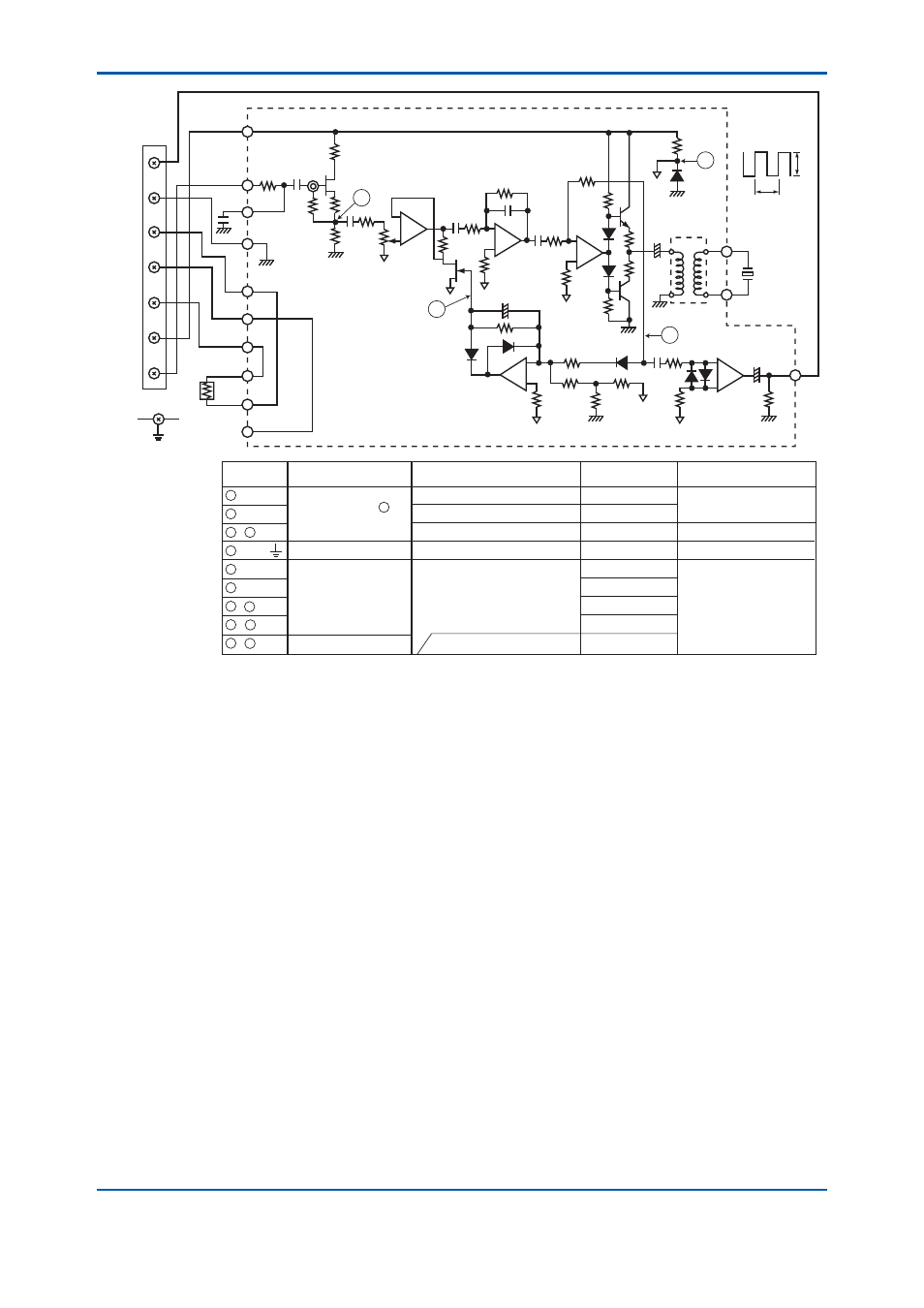
Check point
1
2
3
4
5
6
7
8
9
Measuring instrument
Measuring conditions
Normal value
12 V±10 %
200 V±10 %
5.8 to 6.4 V
;N5DQJH
6 to 8 V p-p
150 to 200 V p-p
200 mV p-p
4 to 6 V p-p
-3 to 0 V
A5 – B5
A6 – B5
B – B5
IN –
B4 – B5
5±%
A – B5
C – B5
D – B5
DC voltmeter
For measurement of 2 ,
the meter input impedance
VKRXOGEHDWOHDVW0ȍ
Multimeter
Oscilloscope
DC voltmeter
Disconnect leadwires from terminals
,15DQG%RQ3&%FRQQHFWDQ
RVFLOODWRUWR+]RXWSXW9
and apply an input of 100 mV rms.
Lower 100 mV rms input
5HPHGLDOPHDVXUH
for abnormal value
&KHFNFRQYHUWHU,1387
assembly.
5HSODFH'
Check pickup electrode.
Check for defective circuit
components and replace
them.
7HUPLQDO
Box
Black
White
Blue
Yellow
Green
Brown
Green
3W
White
A5
A6
IN
B5
A2
A3
A4
Y1
Y2
Y3
5HG
B4
B
5
Black
5HG
3LH]RHOHFWULF
element
Case ground
C
D
B
D8
1mS
6V
A
Vibrator output
wavefarm between
B4 and B5 when
density detector is
operating normally.
(Note) Regading to repair parts, consults with service personnel.
Figure 5.3
Oscillation Amplifi er Check Points