2 main components, 1 density detector, 2 main – Yokogawa DM8C/VD6 Liquid Density Analyzer User Manual
Page 25: Components, 1 density, Detector
< 2. PRINCIPLES OF OPERATION >
2-3
IM 12T03A01-02E
2.2 Main
Components
2.2.1 Density
Detector
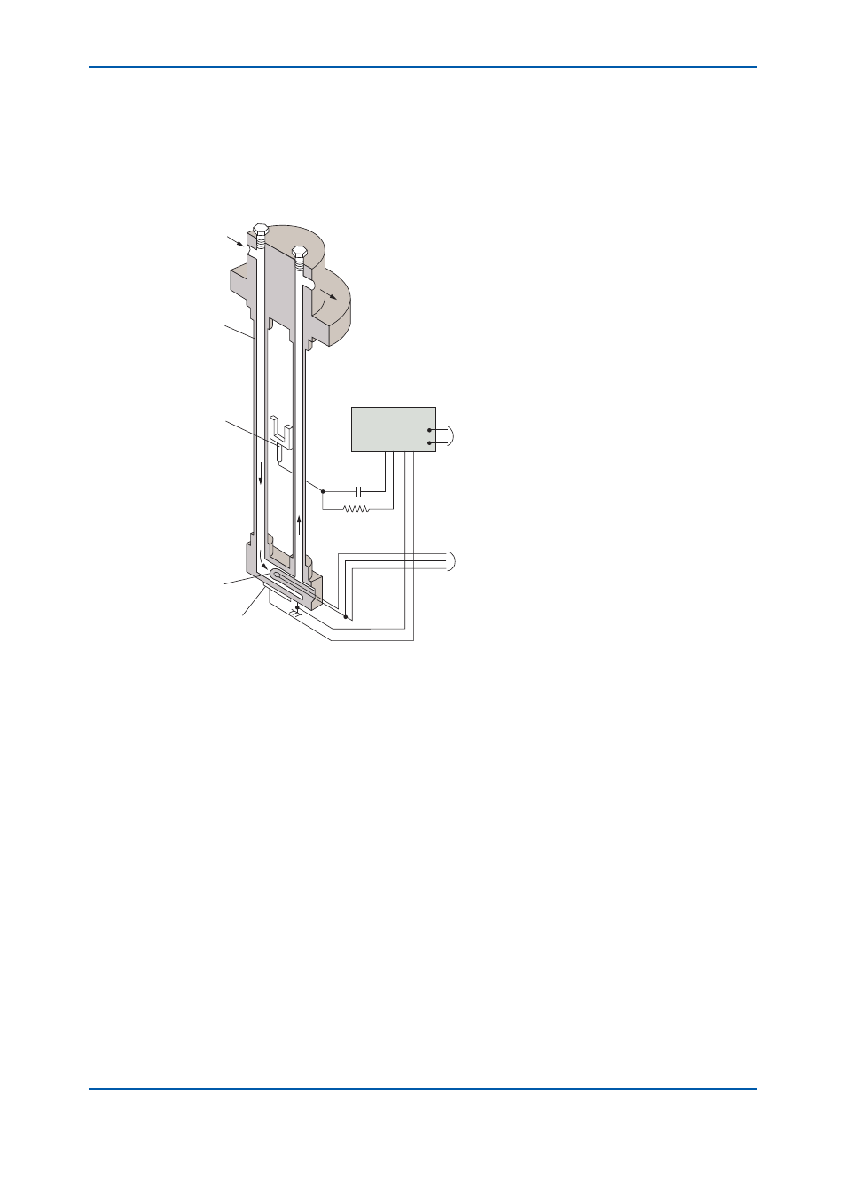
Figure 2.2 is a schematic diagram of the density detector.
As shown in the fi gure, the density detector consists mainly of a vibrator assembly, a capacitance
pickup electrode, and an amplifi er.
Preamplifier
Density signal
Temperature signal
Temperature
measuring element
Vibrator
Sample
Piezo-electric element
Pick-up electrode
Vibrator cross sectional view of Density Detector
Figure 2.2
Schematic Diagram of Density Detector
The vibrator assembly consists of a sample path formed by connecting the ends of two thin tubular
vibrators whose upper ends are connected to a base. The connector incorporates an RTD to measure
the sample liquid temperature. The vibrator assembly also contains a piezoelectric element to
maintain vibration corresponding to the sample liquid density.
The capacitance pickup electrode installed between the two vibrating pipes detects the lateral
oscillation frequency of the vibrator.
The amplifi er converts the output of the capacitance pickup electrode into an AC voltage to amplify
it. This frequency signal is, together with the temperature signal from the RTD, transmitted to the
converter. A part of the frequency signal is fed back to the piezoelectric element to maintain the
vibrator oscillation.