2 air piping for maintenance, 3 steam piping, Air piping for maintenance -11 – Yokogawa DM8C/VD6 Liquid Density Analyzer User Manual
Page 37: 3 steam, Piping
< 3. INSTALLATION, PIPING AND WIRING >
3-11
IM 12T03A01-02E
Sampling unit
Sampling line
Main pipe
Sludge is likely to collect here.
Figure 3.15
Example of Wrong Piping
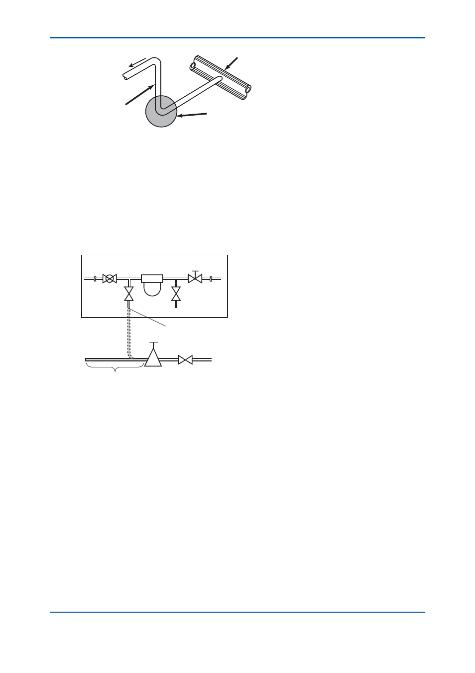
3.3.2 Air Piping for Maintenance
When cleaning the vibrator or calibrating the meter with standard solution, blow away liquid from the
vibrator by air pressure. Air should be clean and dried with 0.3 to 0.5 MPa G.
Mount a ‘stop’ valve and a ‘pressure regulator’ on the pipe from the air source, and fi x a fl exible tube
with a copper tube with outside diameter 10 mm should be provided for connecting with the detector.
Connect the air pipe to the sampling unit only for cleaning the vibrator or calibration with the standard
solution.
Sampling unit
BV1
DD
NV4
NV3
NV2
Stop valve
Reducing
valve
Flexible tube
Connect when cleaning the density detector
Air supply 300 to 500 kPa G
Figure 3.16
Air Piping for Maintenance
3.3.3 Steam
Piping
This is installed to heat measuring liquid whose pour point is high, and to decrease its viscosity. The
sampling unit with steam trace pipes should be used for this purpose.
Connect a pipe from steam source to the sampling unit ‘STEAM IN’ inlet. The sample liquid conduit
also should have a steam tracer pipe. Steam of pressure 0.3 to 0.5 MPa and temperature of 140 to
160 °C is preferable.
Installing the tracer pipe for the sample liquid conduit should be performed after pressure retentive
and leak test of the conduit.
Notes for the tracer piping are as follows.
(1) The tracer pipe of the sample liquid conduit should be installed such that the entire conduit can
be heated. The pipe should also be covered with insulating material (see Figure 3.17).
(2) The steam trap discharge outlet should be open to the atmosphere (see Figure 3.18).