4 turning on the power, 5 data input, Turning on the power -8 – Yokogawa DM8C/VD6 Liquid Density Analyzer User Manual
Page 50: 5 data, Input
< 4. OPERATION >
4-8
IM 12T03A01-02E
(5) Fully open “BV1” and “NV4” and half open “NV1” in the sampling unit. Close ‘drain’ valve opened
in (3). Gradually open the ‘tap’ valve located on the sample inlet conduit. As sample begins to
fl ow out of the ‘drain’ valve on the sample return conduit, fully open the ‘stop’ valve and fully close
the ‘drain’ valve when no retaining air is found in the liquid.
(6) Open “NV2” to exhaust retaining air in the pipe. When the sample liquid without air fl ows out from
the ‘drain’ port, fully close the “NV2”.
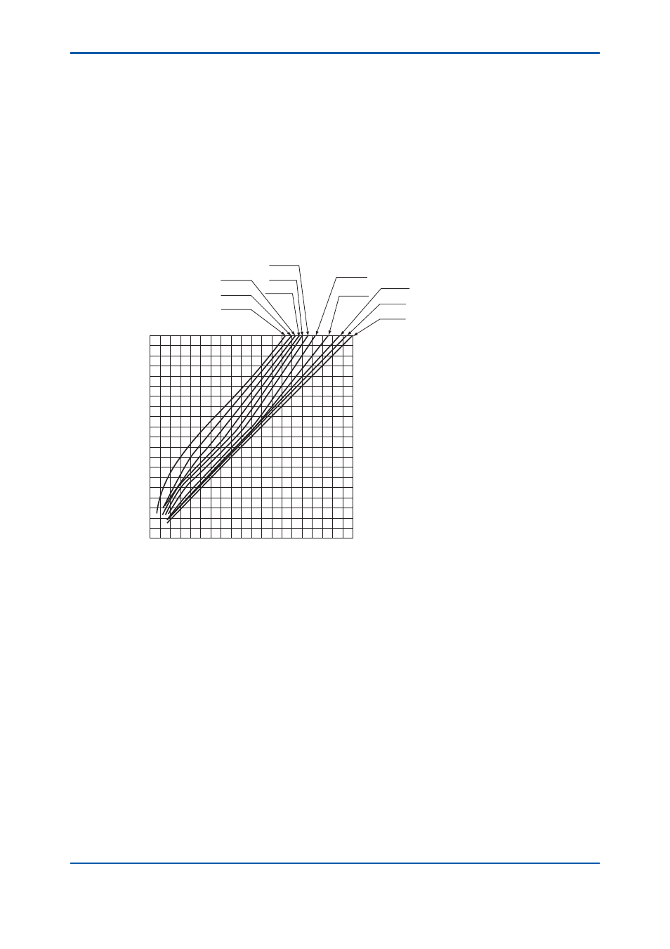
(7) Adjust opening of NV1 to make sample fl ow rate approx. 5 l/min for the detector.
Flow rate shown by FM in the VD6SM sampling unit of Yokogawa varies according to viscosity
of sample. If the viscosity of sample liquid becomes higher, fl ow rate indication also becomes
higher than real fl ow rate (see Figure 4.4).
0
5
10
15
20
5
10
15
20
Actual flow rate (l/min)
Indication of flowmeter (l/min)
Specific gravity of liquid (
ρ=0.85)
15 cP
10 cP
5 cP
1 cP
20 cP
25 cP
30 cP
35 cP
40 cP
50 cP
60 cP
Figure 4.4
Flow Rate Characteristics for Sample Liquid Viscosity
(8) Confi rm that the sample liquid temperature T and pressure P are in the specifi ed range.
(9) Visually check that the sample liquid is not leaking from the connections.
4.3.4 Turning ON the Power
Supply the converter and a receiving unit (recorder, computer, etc.) with power with specifi ed voltage
and frequency. The receiving unit should be ready to receive the data and controller should be
adjusted to perform accurate control.
4.3.5 Data
Input
Set the mode transfer switch to “MAINT” (maintenance mode) and input data to the function No. ‘6.’,
‘7.’, ‘8.’, ‘9.’, ‘A.’ and ‘B.’. For details of data to be input, refer to Section 4.2. Data is input with “SHIFT”,
“INCR” and “SET” keys. For details of these keys operation, refer to Figure 4.1.2.
When temperature coeffi cient of measuring liquid that is to be input into function No. ‘9.’ is unknown
jet, refer to ‘4.4.2 Calibration with Sample Liquid (2)’.