Yokogawa DM8C/VD6 Liquid Density Analyzer User Manual
Page 29
< 3. INSTALLATION, PIPING AND WIRING >
3-3
IM 12T03A01-02E
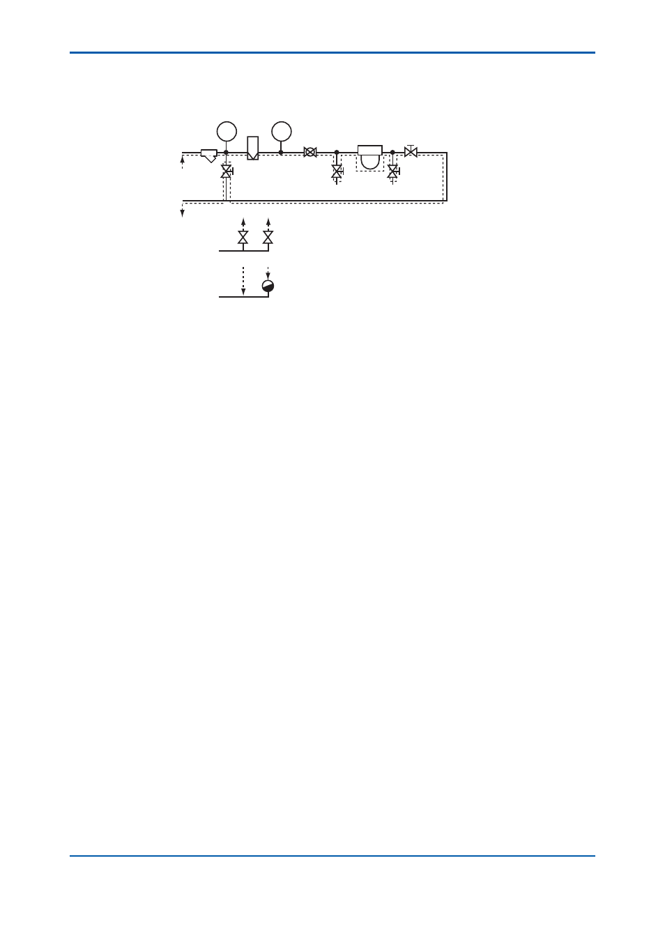
(1) Flow Diagram
Figure 3.5 shows a fl ow diagram of a typical sampling equipment. Model VD6SM sampling unit of
Yokogawa is also designed according to this diagram.
STEAM IN
CONDENSATE OUT
V2
a
a
V1
b
ST1
a'
a'
b'
TI
F
FM
NV1
PI
NV2
DD
NV3
NV4
BV1
Element specifications
F:
Strainer body; SUS316
Element; SUS316, or Ni (option)
PI:
Pressure gauge, 0 to 1MPa or 0 to 2MPa, SUS316
TI:
Thermometer. 0 to 100 °C or 0 to 150 °C, SUS316
FM: Flowmeter, tapered metal tube flowmeter, 1 to 10 l/min, SUS316
BV1: Ball valve, SUS316
NV1 to 4: Needle valve, SUS316
DD: Density
detector
V1, V2: Valve
ST1: Steam trap
SAMPLE IN
SAMPLE OUT
Figure 3.5
Flow Diagram
In Figure 3.5, each element of the sampling equipment is shown F (fi lter) is usually 80 meshes,
prevents a solid from entering into the sampling line. TI (thermometer), FM (fl owmeter) and PI
(pressure gauge) are necessary to monitor measuring liquid. NV1 (needle valve) is required to control
fl ow rate of a sample liquid. BV1 (ball valve) and NV4 (needle valve) are used for stopping measuring
liquid when the vibrator is cleaned or calibration is performed using standard solution. (The needle
valve is also used for adjusting fl ow rate.) NV2 (needle valve) and NV3 (needle valve) are used for
draining liquid from the vibrator or for picking up sample for manual analysis.
When viscosity of a measuring liquid is to be lowered, for example, the pour point of measuring
liquid is high, arrange the density detector and the liquid pipe should be warmed individually. Steam
pipe can be connected to the density detector and the liquid pipe can also be traced by steam pipe.
V1 (“stop” valve) is to supply the steam to the density detector and V2 (“stop” valve) is to supply the
steam to tracing pipe. ST1 (steam trap) is used to drain condensed water.
(Note 1) Kind of valve used in the sampling equipment varies with the purpose of use. This
instruction manual gives a detailed name of equipment (for example, ball valve) used for
limited purpose, and shows a general name within “ ” when equipment type is not restricted (for
example “stop” valve).
(Note 2) Density Detectors of Model VD6D (general purpose type) and VD6DF (fl ameproof) have
steam pipe connections, however, Model VD6DS (sanitary use) has not the connections.
(Note 3) Model VD6SM sampling unit, a product of Yokogawa, is applied to Model VD6D (general
purpose type) or Model VD6DF (fl ameproof type). It is not recommended for the Model VD6DS
(sanitary use) used for food.