1 wiring between detector and converter, Wiring between detector and converter -14 – Yokogawa DM8C/VD6 Liquid Density Analyzer User Manual
Page 40
< 3. INSTALLATION, PIPING AND WIRING >
3-14
IM 12T03A01-02E
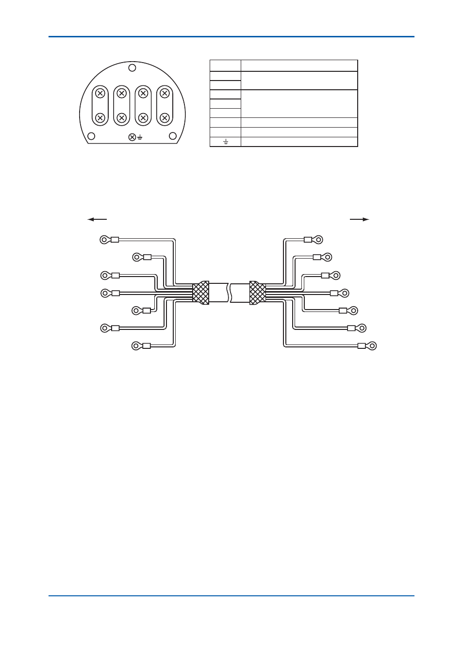
Figure 3.21 shows terminal arrangement of the density detector.
A2
A3
A5
B4
A4
A6
B5
Terminals
Function
B4
B5
A2
A3
A4
A5
A6
Output Frequency
Temperature Sensor
Power Supply for Pre-amp
Impressed Voltage for Pick-up Electrode
Earth Terminal
Figure 3.21
Terminal Arrangement of Density Detector
3.4.1 Wiring between Detector and Converter
This wiring is to be carried out with special cable of specifi ed length. The cable is terminated as
illustrated in Figure 3.22. Pay attention not to stain or wet terminated.
GRAY
YELLOW
BROWN
RED
RED
WHITE
WHITE
BLUE
BLUE
GREEN
GREEN
BROWN
YELLOW
GRAY
Density detector
Density converter
B4
B5
A4
A2
A3
A5
A6
B4
B5
A2
A3
A4
A5
A6
Figure 3.22
DM8W Cable
(Connection to Density Detector)
Remove the cover of the terminal box, using the spanner in accessories, and insert the special cable
into the cable inlet. Connect each conductor to the respective terminals.
A fl exible fi tting is used at the inlet of the density detector (note) and the cable from the detector runs
though metal conduit to the duct. For Model VD6DF explosionproof detector, wiring should be made
complying with the Recommended Practice.
The explosionproof fl exible fi tting for wiring should be used at the cable inlet (G3/4 female) of the
detector.
(Note) The fl exible fi tting is not inevitable. The Detector not moved for usual check or maintenance
does not require the fl exible tube.