4 wiring – Yokogawa DM8C/VD6 Liquid Density Analyzer User Manual
Page 39
< 3. INSTALLATION, PIPING AND WIRING >
3-13
IM 12T03A01-02E
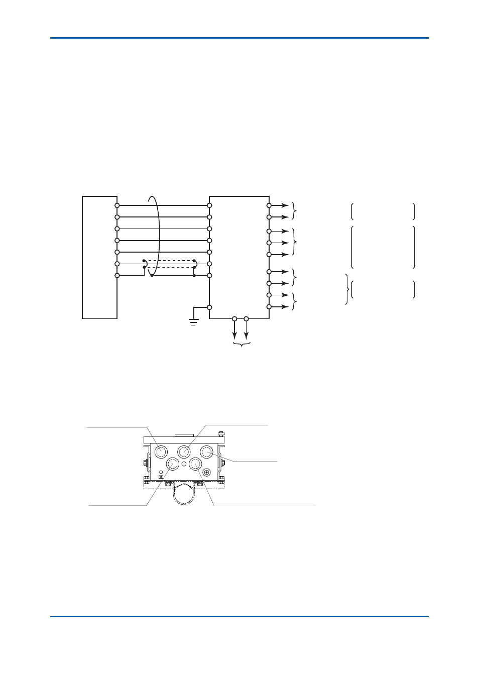
3.4 Wiring
The vibration type density meter requires the following wirings:
(1) Wiring between analog output signal
(2) Wiring for analog output signal
(3) Wiring for digital output signal (10 m or less length is recommended).
(4) Wiring for contact output for abnormal status
(5) Wiring for power supplying
(6) Wiring for grounding
Figure 3.19 is a diagram of these wirings.
A2
A3
A4
A6
A5
B4
B5
A2
A3
A4
A6
A5
B4
B5
RED
BLUE
YELLOW
BROWN
GREEN
WHITE
GRAY
N.C
C
SG
RD
TD
+
-
+
-
G
L1 L2
Detector
Special cable
Converter
Power supply
Alarm
0 to 1 V DC
4 to 20 mA DC
RS-232-C signal
Closed when a
failure is detected or
the power fails.
Density signal after being
converted to the reference
temperature state
Density signal before being
converted to the reference
temperature state
7HPSHUDWXUHVLJQDO
Density signal after being
converted to the reference
temperature state
Figure 3.19
Wiring Diagram
The cable inlet of the density detector is located at the bottom of the terminal box. The density
converter has fi ve cable inlets and their size is 27 mm. A cable can pass any inlet of them (one cable
to one inlet). Figure 3.20 shows an example of allocated inlets.
Power supply
Contact output for abnormal status
Digital output signal
Inlet of special cable
Analog output signal
Figure 3.20
Cable Inlet of Density Converter