2 density converter, 2 density, Converter – Yokogawa DM8C/VD6 Liquid Density Analyzer User Manual
Page 26: And temperature signal (voltage) v, Figure 2.3 block diagram of density converter
< 2. PRINCIPLES OF OPERATION >
2-4
IM 12T03A01-02E
2.2.2 Density
Converter
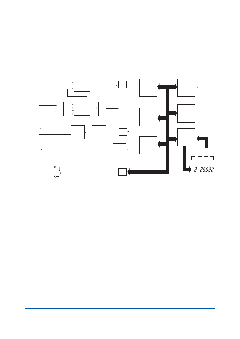
Figure 2.3 is a block diagram of the density converter.
As shown in the diagram, the density converter receives the density signal (frequency) F
ρ
and
temperature signal (voltage) V
T
from the density detector and fi nally outputs a 4 to 20 mA analog
signal and 0 to 1 V DC signal corresponding to the liquid density converted to that at reference
temperature. The digital signals of densities at measuring temperature and reference temperature,
and measuring temperature and measuring temperature value are also output. The converter circuit
comprises three printed circuit boards. Changing displayed items or setting constants are performed
by keys or transfer switches on the front panel.
CPU
Memory
ROM
RAM
EEPROM
Key &
Display
Controller
W.D.T.
PC
0 to 1 V
4 to 20 mA
Key
LED
TD
Digital Output
Fail Alarm
200 V
Reference frequency
Ref. temp. Zero
Frequency of Density (Fx)
Temp. Signal
(RT)
R/V
Ref. temp. Span
Multiplexer
Multiplexer
V/F
Integrator
V/I
Zero
Span
Driver
PC
PC
PC
COUNTER
P.W.
Modulation
Serial
Communi-
cation
Controller
Figure 2.3
Block Diagram of Density Converter