2-2 host setting, 2-3 bus power on, 2-2 host setting -4 – Yokogawa DO202 2-Wire Dissolved Oxygen Analyzer User Manual
Page 9: 2-3 bus power on -4, Important
IM 12A00A01-61E
3-4 Foundation Fieldbus
3-2-2 Host Setting
To activate Fieldbus, the following settings are required for the host.
IMPORTANT
Do not turn off the power immediately after setting. When the parameters are saved to the EEPROM, the
redundant processing is executed for an improvement of reliability. If the power is turned off within 60 seconds after
setting is made, the modified parameters are not saved and the settings may return to the original values.
Table 3.1 Operation Parameters
Symbol
Parameter
Description and Settings
V (ST)
Slot-Time
Set 4 or greater value.
V (MID)
Minimum-Inter-PDU-Delay
Set 4 or greater value.
V (MRD) Maximum-Reply-Delay
Set so that V (MRD) X V (ST) is 12 or greater
V (FUN)
First-Unpolled-Node
Define the first address that can be used by the host. Set 0x15 or greater.
V (NUN)
Number-of-consecutive-Unpolled-Node
This sets the number of consecutive unpolled nodes. EXA address is
factory-set to 0xEB. Set this address to be within the range of the BASIC
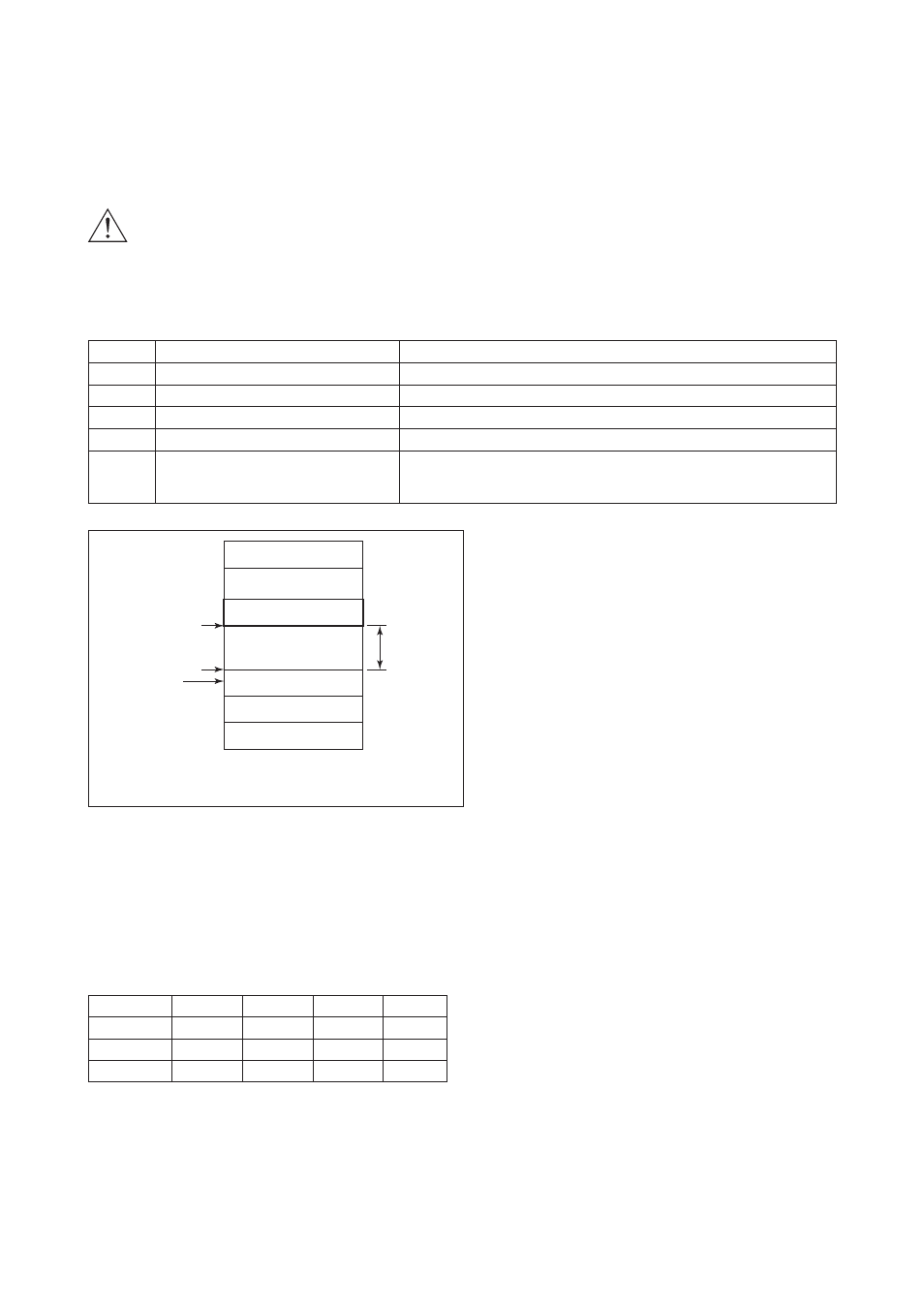
device in Figure 3.5.
Not used
LM device
Not used
Basic device
Default address
Portable-device address
V (FUN)
V (FUN) + V (NUN)
V (NUN)
0xFF
0xFC
0xFB
0xF8
0xF7
0x00
0x0F
0x10
0x13
0x14
Bridge device
Note 1: LM device: with bus control function (Link Master function)
Note 2: BASIC device: without bus control function
EXA
Figure 3.5 Available Address Range
3-2-3 Bus Power ON
Turn on the power of the host and the bus. First all segments of the display are lit, then the display begins
to operate. If the indicator is not lit, check the polarity of the power supply.
Using the host device display function, check that the EXA is in operation on the bus.
Unless otherwise specified, the following settings are in effect when shipped from the factory.
PH202
SC202
ISC202
DO202
PD tag
PH1001
SC1001
ISC1001
DO1001
Node addr.
232
233
234
235
DEV_TYPE
0x0830
0x0831
0x0832
0x0833
If no EXA is detected, check the available address range and the polarity of the power supply. If the node
address and PD tag are not specified when ordering, default value is factory set. If two or more EXA’s are
connected at a time with default value, only one EXA will be detected from the host as EXA’s have the
same initial address.
Separately connect each EXA and set a different address for each.