1-4 wiring system configuration, 2 getting started, 2-1 connection of devices – Yokogawa DO202 2-Wire Dissolved Oxygen Analyzer User Manual
Page 7: 2-1-1. fieldbus preparation, 1-4 wiring system configuration -2, 2 getting started -2, 2-1 connection of devices -2, 2-1-1. fieldbus preparation -2
IM 12A00A01-61E
3-2 Foundation Fieldbus
3-1-4 Wiring System Configuration
The number of devices that can be connected to a single bus and the cable length vary depending on sys-
tem design. When constructing systems, both the basic and overall design must be carefully considered to
allow device performance to be fully exhibited.
3-2 Getting started
Fieldbus is fully dependent upon digital communication protocol and differs in operation from conventional
4 to 20 mA transmission communication protocol. It is recommended that novice users use field devices in
accordance with the procedures described in this section. The procedures assume that field devices will be
set up on a bench or an instrument shop.
3-2-1 Connection of Devices
3-2-1-1. Fieldbus Preparation
The Foundation Fieldbus
®
connections and the sensor connections should be made in accordance with fig-
ure 3.2 and 3.3. The terminals are of a plug in style for ease of mounting.
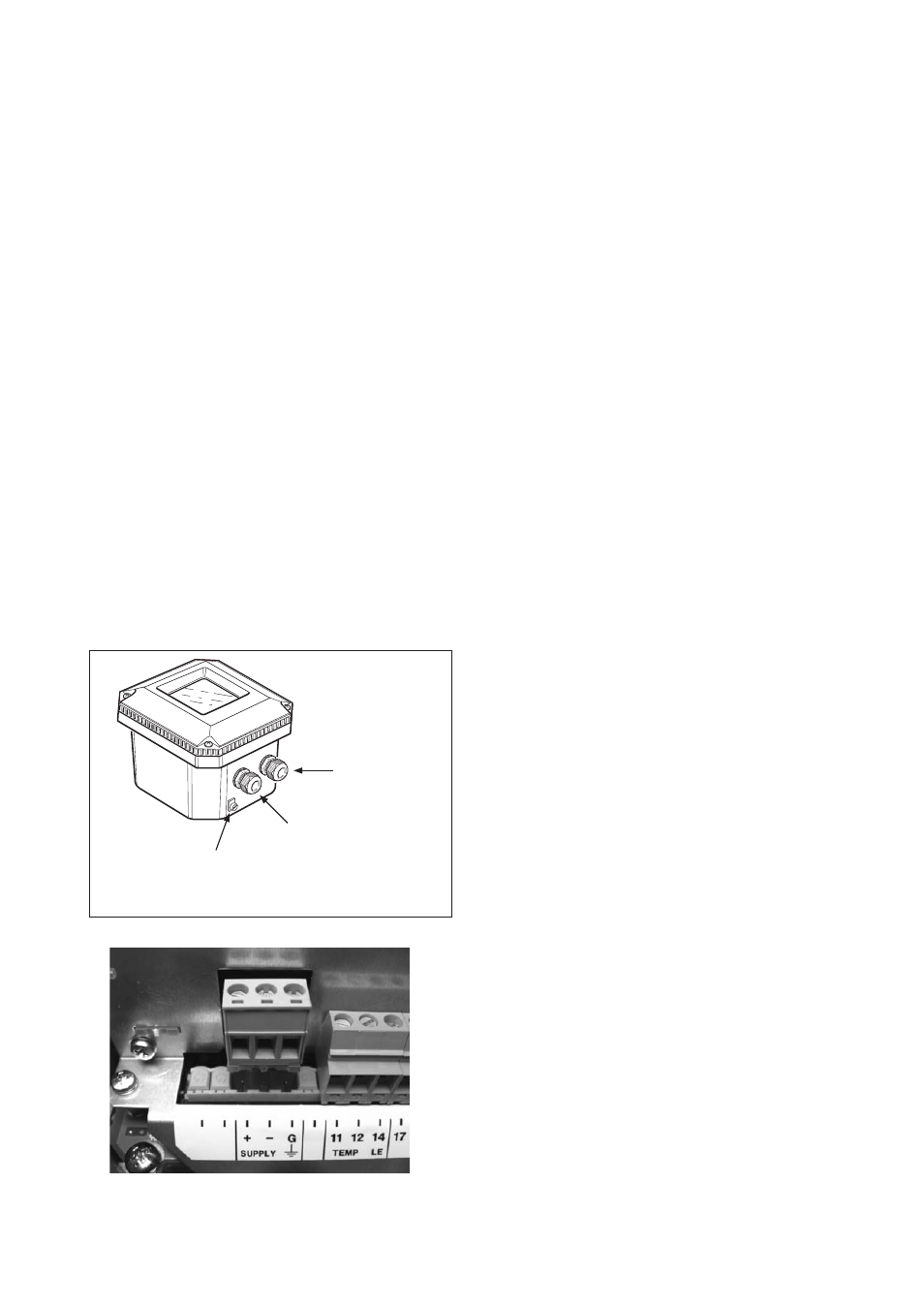
The EXA 202 FF is provided with two cable glands. The first is used for the electrode wiring as the other is
used for the power/foundation
®
Fieldbus wiring shown in figure 3.2.
To open the EXA 202 for wiring:
1. Loosen the four frontplate screws and remove the cover.
2. The terminal strip is now visible.
3. Connect the power supply to the green connector according figure 3.3. Use the gland on the left for this
cable.
4. Connect the sensor input, using the gland on the right (see figure 3.2). Switch on the power.
Commission the instrument as required or use the default settings.
5. Replace the cover and secure frontplate with the four screws.
Sensor cable
gland
Foundation Fieldbus®
cable gland
Grounding terminal
(connect to safety ground,
only if power supply is not grounded)
Figure 3.2 Glands to be used for cabling
Figure 3.3 Green connector for power supply