3-3 definition of combining function blocks, 3-3 definition of combining function blocks -8 – Yokogawa DO202 2-Wire Dissolved Oxygen Analyzer User Manual
Page 13
IM 12A00A01-61E
3-8 Foundation Fieldbus
Table 3.3 Operation Parameter Values of the EXA to be Set to LM Devices
Symbol
Parameters
Description and Settings
V (ST)
Slot-Time
Indicates the time necessary for immediate reply of the device. Unit of time is in octets
(256 µs). Set maximum specification for all devices.
For EXA, set a value of 4 or greater.
V (MID)
Minimum-Inter-PDU-Delay
Minimum value of communication data intervals. Unit of time is in octets (256 µs). Set the
maximum specification for all devices.
For EXA, set a value of 4 or greater.
V (MRD)
Maximum-Reply-Delay
The worst case time elapsed until a reply is recorded. The unit is Slot-time; set the value
so that V (MRD) 3V (ST) is the maximum value of the specification for all devices.
For EXA, the setting must be a value of 12 or greater.
3-3-3 Definition of Combining Function Blocks
The input/output parameters for function blocks are combined. For the EXA, three AI blocks output param-
eter (OUT) are subject to combination. They are combined with the input of the control block as necessary.
Practically, setting is written to the EXA link object with reference to “Block setting” in Section 3-3-6 for
details. It is also possible to read values from the host at proper intervals instead of connecting the EXA
block output to other blocks.
The combined blocks need to be executed synchronously with other blocks on the communications sched-
ule. In this case, change the EXA schedule according to the following table. Enclosed values in the table
are factory-settings.
Table 3.4 Execution Schedule of the EXA Function Blocks
Index
Parameters
Setting (Enclosed is factory-setting)
269(SM)
MACROCYCLE_DURATION
Cycle (MACROCYCLE) period of control or measurement. Unit is 1/32 ms. (32000
= 1 s)
276(SM)
FB_START_ENTRY.1
AI1 block startup time. Elapsed time from the start of MACROCYCLE specified in
1/32 ms. (0 = 0 s)
277(SM)
FB_START_ENTRY.2
AI2 block startup time. Elapsed time from the start of MACROCYCLE specified in
1/32 ms. (9600 = 0.3 s)
278(SM)
FB_START_ENTRY.3
AI3 block startup time. Elapsed time from the start of MACROCYCLE specified in
1/32 ms. (19200 = 0.6 s)
279(SM) to
289(SM)
FB_START_ENTRY.4 to 14
Not used.
A maximum of 29 ms is taken for execution of an AI block. Executions of AI blocks should be scheduled
sequentially. In no case should two AI function blocks of the EXA be executed at the same time (execution
time is overlapped). 29 ms after AI block execution start the out value is available for further processing.
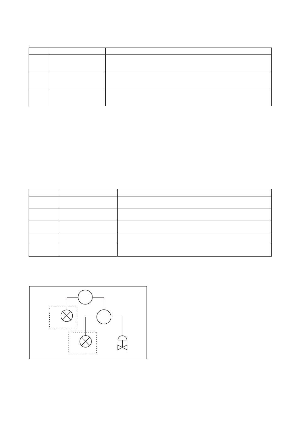
Figure 3.8 shows an example of schedule based on the loop shown in Figure 3.7.
LIC100
FIC100
FC100
FI100
EXA
#2
LI100
EXA
#1
Figure 3.7 Example of Loop Connecting Function Block of Two EXA with Other Instruments