Foundation fieldbus, 1 about foundation fieldbus, 1-1 outline – Yokogawa DO202 2-Wire Dissolved Oxygen Analyzer User Manual
Page 6: 1-2 internal structure of exa, 1-2-1 system/network management vfd, 1-2-2 function block vfd, 1-3 logical structure of each block, Foundation fieldbus -1, 1 about foundation fieldbus -1, 1-1 outline -1
IM 12A00A01-61E
Foundation Fieldbus 3-1
3. FOUNdATION FIELdBUS
3-1 About Foundation Fieldbus
3-1-1 Outline
Fieldbus is a bi-directional digital communication protocol for field devices, which offers an advance-
ment implementation technologies for process control systems and is widely employed by numerous
field devices.
EXA Series Fieldbus communication type employs the specification standardized by The Fieldbus
Foundation, and provides interoperability between Yokogawa devices and those produced by other
manufacturers. Fieldbus comes with software consisting of three AI function blocks, providing the
means to implement flexible instrumentation system.
For information on other features, engineering, design, construction work, startup and maintenance of
Fieldbus, refer to http://www.yokogawa.com/fbs/fbs-index.htm.
3-1-2 Internal Structure of EXA
The EXA contains two virtual field devices (VFD) that share the following functions.
3-1-2-1 System/network Management vFd
• Sets node addresses and Physical Device tags (PD Tag) necessary for communication
• Controls the execution of function blocks
• Manages operation parameters and communication resources (Virtual Communication Relationship:
VCR)
3-1-2-2 Function Block vFd
(1) resource block
• Manages the status of EXA hardware
• Automatically informs the host of any detected
faults or other problems
(2) Transducer block
• Converts sensor output to process values and
transfers to AI function block by channels
(3) AI1, AI2, AI3 function block
• Conditions raw data from the Transducer block
• Outputs conditioned process values
• Carries out scaling, damping and square root
extraction
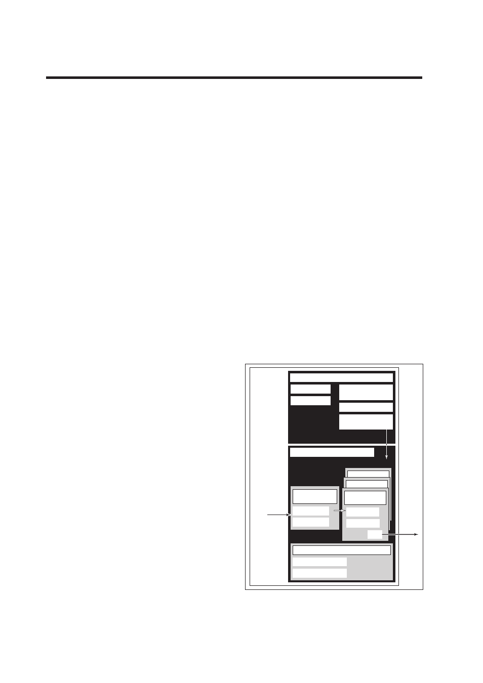
3-1-3 Logical Structure of Each Block
Setting of various parameters, node addresses, and
PD Tags shown in Figure 3.1 is required before
starting operation.
System/network management VFD
Function block VFD
PD Tag
Sensor
input
Resource block
Block tag
Parameters
Communication
parameters
VCR
Node address
Function block
execution schedule
AI function
block
AI function
block
Output
AI function
block
Block tag
OUT
Parameters
Transducer
block
Block tag
Parameters
Sensor
Figure 3.1 Logical Structure of Each Block