A1-3 transfer of las, A1-3 transfer of las -2 – Yokogawa DO202 2-Wire Dissolved Oxygen Analyzer User Manual
Page 80
5-2 APPENDIX 1. LINK MASTER FUNCTIONS
IM 12A00A01-61E
A1-3 Transfer of LAS
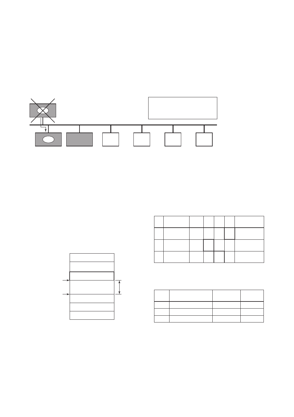
There are two procedures for an LM to become the LAS:
• If the LM whose value of [V(ST)3V(TN)] is the smallest on a segment, with the exception of the current
LAS, judges that there is no LAS on the segment, in such a case as when the segment has started up or
when the current LAS has failed, the LM declares itself as the LAS, then becomes the LAS. (With this
procedure, an LM backs up the LAS as shown in the following figure.)
• The LM whose value of [V(ST)3V(TN)] is the smallest on a segment, with the exception of the current
LAS, requests the LAS on the same segment to transfer the right of being the LAS, then becomes the
LAS.
LM
Node address:
0x15
SlotTime = 5
LM
Node address:
0x16
SlotTime = 5
Node address: 0x14
SlotTime = 5
Basic device
Node address:
0xF1
Basic device
Node address:
0xF2
Basic device
Node address:
0xF3
Basic device
Node address:
0xF4
LAS
LAS
In the event that the current LAS in
this segment (node address 0x14)
fails, the LM with the address of 0x15
takes its place to become the LAS.
LM
Figure A1-2. Backup of LAS
To set up a EXA202 as a device that is capable of
backing up the LAS, follow the procedure below.
NOTE: When changing the settings in a EXA202,
add the EXA202 to the segment in which an
LAS is running. After making changes to
the settings, do not turn off the power to the
EXA202 for at least 60 seconds.
(1) Set the node address of the EXA202.
In general, use an address from 0x14 to
[V(FUN) – 1].
Not used
LM device
Not used
Basic device
Default address
Portable-device address
V (FUN)
V (FUN) + V (NUN)
V (NUN)
0xFF
0xFC
0xFB
0xF8
0xF7
0x00
0x0F
0x10
0x13
0x14
Bridge device
Figure A1-3. Node Address ranges
(2) In the LAS settings of the EXA202, set the
values of V(ST), V(MRD), and V(MID) to
the same as the respective lowest capability
values in all the devices within the segment.
An example is shown below.
Sub-
index
Element
Device
1
Device
2
Device
3
Description
1
3
6
SlotTime
MaxResponse
Delay
MinInterPdu
Delay
4
3
4
8
6
8
10
3
12
20
5
10
Capability value
for V(ST)
Capability value
for V(MRD)
Capability value
for V(MID)
DlmeBasicInfo (EXA202 Index 361 (SM))
EXA202
In this case, set SlotTime, MaxResponseTime,
and MinInterPduDelay as follows:
Subindex
Element
ConfiguredLinkSettingsRecord
(EXA202 Index 369 (SM))
Description
Setting
(Default)
V (ST)
V (MRD)
V (MID)
20
6
12
(4095)
(5)
(12)
SlotTime
MaxResponseDelay
MinInterPduDelay
1
3
6