A1-5-2 descriptions for lm parameters, A1-5-2 descriptions for lm parameters -6 – Yokogawa DO202 2-Wire Dissolved Oxygen Analyzer User Manual
Page 84
5-6 APPENDIX 1. LINK MASTER FUNCTIONS
IM 12A00A01-61E
A1-5-2 descriptions for LM Parameters
The following describes LM parameters of a
EXA202 transmitter.
NOTE: Do not turn off the power to the EXA202
for 60 seconds after making a change to its
parameter settings.
(1) dlmeLinkMasterCapabilitiesvariable
Meaning
Bit
Position
Value
Description
1
0
0
LAS Schedule
in Non-volatile
Memory
Last Values
Record
Supported
Link Master
Statistics
Record
Supported
Whether the LAS schedule can
(= 1) or cannot (= 0) be saved
to the non-volatile memory
Whether to support (= 1) or not
to support (= 0)
LastValuesRecord.
Whether to support (= 1) or not
to support (= 0)
DlmeLinkMasterStatisticsRecord.
B3: 0x04
B2: 0x02
B1: 0x01
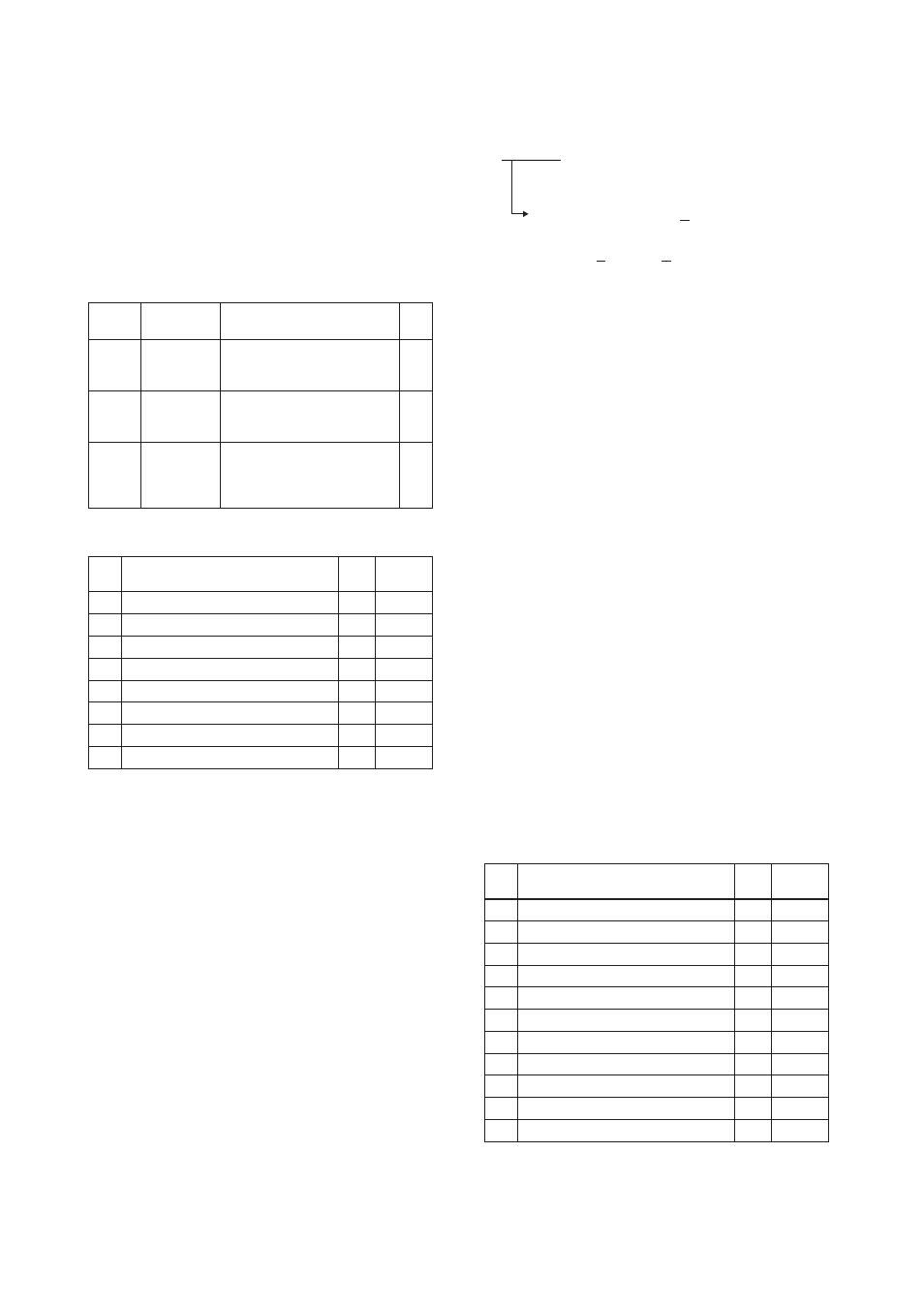
(2) dlmeLinkMasterInforecord
Element
Sub-
index
Descrip-
tion
Size
[bytes]
1
2
2
2
2
4
2
2
V(MSO)
V(DMDT)
V(DTHT)
V(TTRT)
V(LTHT)
V(TDP)
V(MICD)
V(LDDP)
MaxSchedulingOverhead
DefMinTokenDelegTime
DefTokenHoldTime
TargetTokenRotTime
LinkMaintTokHoldTime
TimeDistributionPeriod
MaximumInactivityToClaimLasDelay
LasDatabaseStatusSpduDistributionPeriod
1
2
3
4
5
6
7
8
(3) PrimaryLinkMasterFlagvariable
Explicitly declares the LAS. Writing “true” (0xFF)
to this parameter in a device causes that device to
attempt to become the LAS. However, a request
of writing “true” to this parameter in a device is
rejected if the value of the same parameter in
any other device that has a smaller node address
within the same segment is true.
(4) LiveListStatusArrayvariable
A 32-byte variable, in which each bit represents
the status of whether a device on the same seg-
ment is live or not. The leading bit corresponds
to the device address 0x00, and final bit to 0xFF.
The value of LiveListStatusArrayVariable in the
case where devices having the addresses 0x10
and 0x15 in the fieldbus segment is shown below.
0x00 00 84 00 00 00 00 00 00 00 00 00 00 00
00 00 00 00 00 00 00 00 00 00
00 00 00 00 00 00 00 00
Bit correspondences: 0 0 0 0 0 0 0 0 0 0 0
0Ч00
0 0 0 0 0 1 0 0 0 0 1 0 0...
0Ч10
0Ч15
(5) MaxTokenHoldTimeArray
An 8- by 64-byte array variable, in which each set
of 2 bytes represents the delegation time (set as
an octet time) assigned to a device. The delega-
tion time denotes a time period that is given to a
device by means of a PT message sent from the
LAS within each token circulation cycle.
The leading 2 bytes correspond to the device
address 0x00, and the final 2 bytes to the device
address 0xFF. Specify the subindex to access
this parameter.
(6) BootOperatFunctionalClass
Writing 1 to this parameter in a device and restart-
ing the device causes the device to start as a
basic device. On the contrary, writing 2 to this
parameter and restarting the device causes the
device to start as an LM.
(7) CurrentLinkSettingrecord and Config-
uredLinkSettingsrecord
CurrentLinkSettingRecord indicates the bus
parameter settings currently used. ConfiguredL
inkSettingsRecord indicates the bus parameter
settings to be used when the device becomes
the LAS. Thus, when a device is the LAS, its
CurrentLinkSettingRecord and ConfiguredLinkSetti
ngsRecord have the same values.
Element
Sub-
index
Descrip-
tion
Size
[bytes]
2
1
1
1
2
1
1
1
1
1
1
V(ST)
V(PhLO)
V(MRD)
V(FUN)
V(TL)
V(MID)
V(NUN)
V(PhPE)
V(PhGE)
V(PhIS)
V(TSC)
SlotTime
PerDlpduPhlOverhead
MaxResponseDelay
FirstUnpolledNodeId
ThisLink
MinInterPduDelay
NumConsecUnpolledNodeId
PreambleExtension
PostTransGapExtension
MaxInterChanSignalSkew
TimeSyncClass
1
2
3
4
5
6
7
8
9
10
11