2. preparation, 2-1. cables, terminals and glands, 2-2. shielding and grounding – Yokogawa DO202 2-Wire Dissolved Oxygen Analyzer User Manual
Page 62: 2. preparation -4
4-4 Profibus
IM 12A00A01-61E
4-2. Preparation
The EXA 202 Profibus is provided with two cable glands. The first is used for the electrode wiring as the
other is used for the power wiring shown in figure 4.3.
To open the EXA 202 for wiring:
1. Loosen the four frontplate screws and remove the cover.
2. The terminal strip is now visible.
3. Connect the power supply according figure 4.4. Use the gland on the left for this cable.
4. Connect the sensor input, using the gland on the right (see figure 4.3). Switch on the power.
Commission the instrument as required or use the default settings.
5. Replace the cover and secure frontplate with the four screws.
4-2-1. Cables, terminals and glands
The EXA202 is equipped with terminals suitable for the connection of finished cables in the size range:
0.13 to 2.5 mm (26 to 14 AWG). The glands will form a tight seal on cables with an outside diameter in the
range of 6 to 12 mm (0.24 to 0.47 inches).
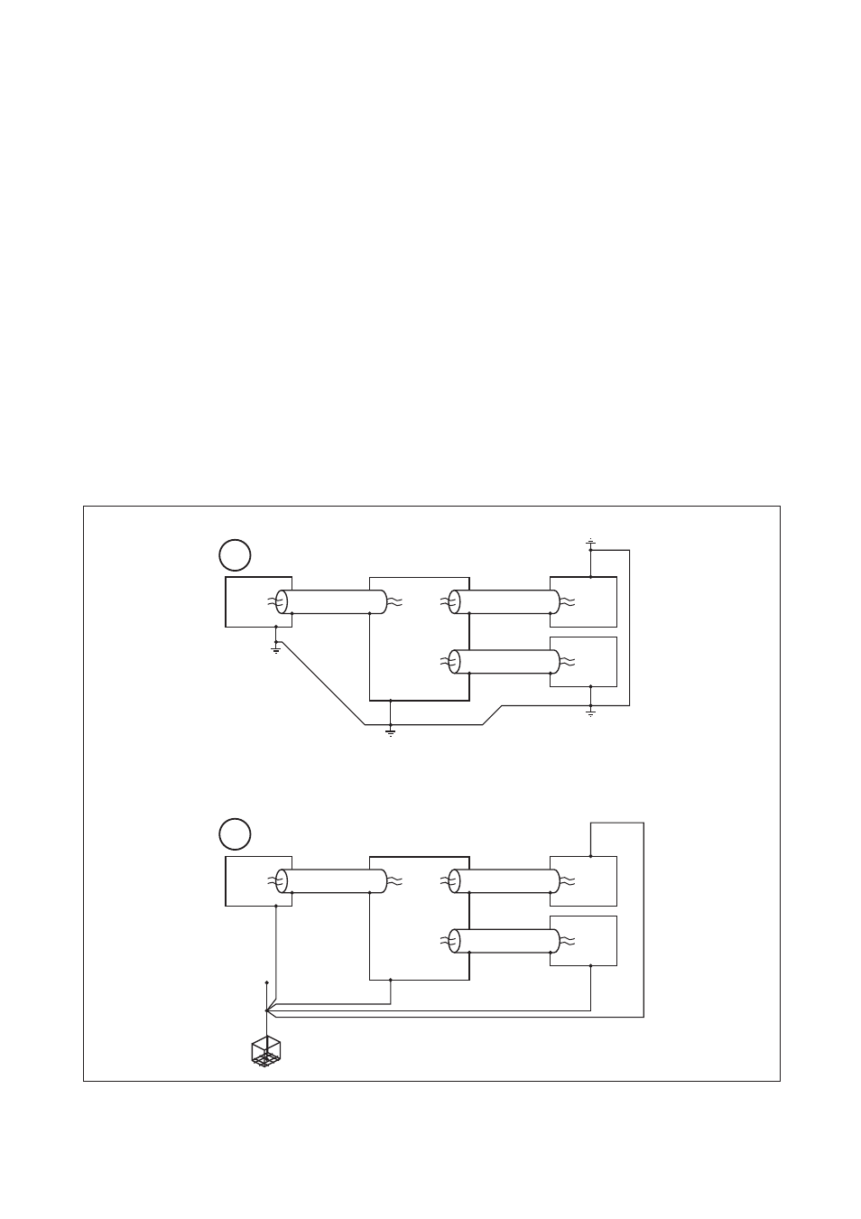
4-2-2. Shielding and grounding
Grounding and shielding of the transmitter is necessary for a safe and reliable operation. Please use one of
the following schemes (A or B) as these will give proper shielding and grounding. One should pay special
attention to instruments that required an external power supply (besides the 9-32V supplied by the bus).
Power
unit
trunck cable
Spur
Spur
Field
device
Field
device
Junction
box
V
1
V
3
V
2
V
4
V
1 =
V
2 =
V
3 =
V
4
Potential equalisation line (German practice)
Power
unit
trunck cable
Spur
Spur
Field
device
Field
device
Junction
box
High integrity eart, 0.1R or better
Neutral star-point bonding (English practice)
A
B
Figure 4.6 Shielding and grounding