3-2 network definition, 3-2 network definition -7 – Yokogawa DO202 2-Wire Dissolved Oxygen Analyzer User Manual
Page 12
IM 12A00A01-61E
Foundation Fieldbus �-�
�-�
First, check the capacity of the power supply. The power supply capacity must be greater than the sum of
the maximum current consumed by all devices to be connected to Fieldbus. The maximum current con-
sumed (power supply voltage 9 to �2 V) for EXA is 26.0 mA. The cable must have the spur in a minimum
length with terminators installed at both ends of the trunk.
3-3-2 Network Definition
Before connection of devices with Fieldbus, define the Fieldbus network. Allocate PD Tag and node
addresses to all devices (excluding such passive devices as terminators).
The PD Tag is the same as the conventional one used for the device. Up to �2 alphanumeric characters
may be used for definition. Use a hyphen as a delimiter as required.
The node address is used to specify devices for communication purposes. Because data is too long for a
PD Tag, the host uses the node address in place of the PD Tag for communication.
A range of 20 to 24� (or hexadecimal 0x14 to 0xF�) can be set.
Addresses of devices with Link Master capabilities are set in a low address range smaller than V(FUN).
Addresses of basic devices are set in a higher range bigger than V(FUN) + V(NUN).
Specify the adress range used by setting the following two parameters in the LM-device:
Table 3.2 Parameters for Setting Address Range
Symbol
Parameters
Description
V (FUN)
First-Unpolled-Node
Indicates the address next to the address range used for the host or other
LM device.
V (NUN) Number-of-consecutive-Unpolled-Nodes
Unused address range
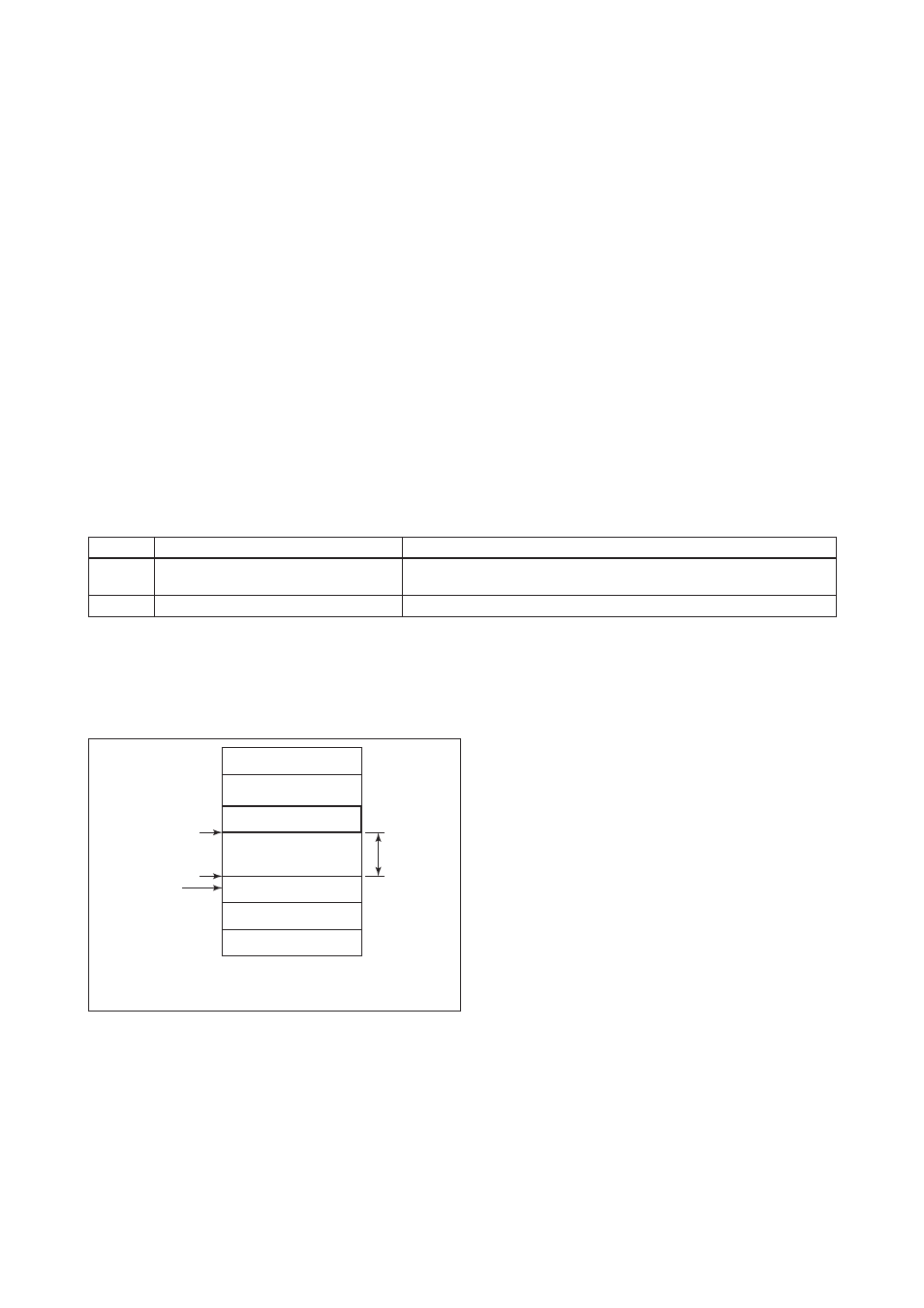
The devices within the address range written as “Not used” in Figure �.6 cannot be used on a Fieldbus. For
other address ranges, the range is periodically checked to identify when a new device is connected. Care
must be taken not to allow the address range to become wider, which can lead to exhaustive consumption
of Fieldbus communication performance.
Not used
LM device
Not used
Basic device
Default address
Portable-device address
V (FUN)
V (FUN) + V (NUN)
V (NUN)
0xFF
0xFC
0xFB
0xF8
0xF7
0x00
0x0F
0x10
0x13
0x14
Bridge device
Note 1: LM device: with bus control function (Link Master function)
Note 2: BASIC device: without bus control function
(EXA 0xEB)
Figure 3.6 Available Range of Node Addresses
To ensure stable operation of Fieldbus, determine the operation parameters and set them to the LM devic-
es. While the parameters in Table �.� are to be set, the worst-case values of all the devices to be connect-
ed to the same Fieldbus must be used. Refer to the specification of each device for details. Table �.� lists
EXA specification values.