Normal operating condition, Terminal connection, Accessories – Yokogawa ADMAG AXF User Manual
Page 91: Model and suffix code, Caution
IM 1E10C1-E
10-2
10. OUTLINE
Maximum Power Consumption:
11W for SE***DJ/EJ+SE14
Insulation Resistance:
• 100M
Ω
between power terminals and ground
terminal at 500V DC.
• 100M
Ω
between power terminals and each
output terminal at 500V DC.
• 20M
Ω
between each output terminal (except
for EX1 and EX2) and ground terminal at 100V
DC.
• 20M
Ω
between (EX1 or EX2) and ground ter-
minal at 50V DC.
Withstand Voltage:
• 1500V AC between power terminals and
ground terminal for 1 minute. (for -A1/A2 power
supply)
• 500V AC between power terminals and ground
terminal for 1 minute. (for -D1 power supply)
CAUTION
When performing the Voltage Breakdown Test,
Insulation Resistance Test or any unpowered
electrical test, wait 10 seconds after the power
supply is turned off before removing the housing
cover. Be sure to remove the Short Bar at terminal
“G”. After testing, return the Short Bar to its correct
position. Screw tightening torque should be 1.18N-
m(0.88ft-lb)or more, because the G-terminal is
thought as a protective grounding and should
conform to the Safety Requirements.
Safety Requirement Standard:
IEC1010, EN61010
EMC Conformity Standard:
EN61326
EN61000-3-2, EN61000-3-3
AS/NZS 2064
■
NORMAL OPERATING CONDITION
Ambient Temperature: -20 to 60
°
C (-4 to 140
°
F)
Ambient Humidity: 5 to 95%RH (no condensation)
Rated Power Supply Voltage:
100V AC/DC Version:
Range 80 to 127V AC, 47 to 63Hz
90 to 110V DC
230V AC Version: Range 180 to 264V AC
24V DC/AC Version:
Range 20.4 to 28.8 V DC/AC
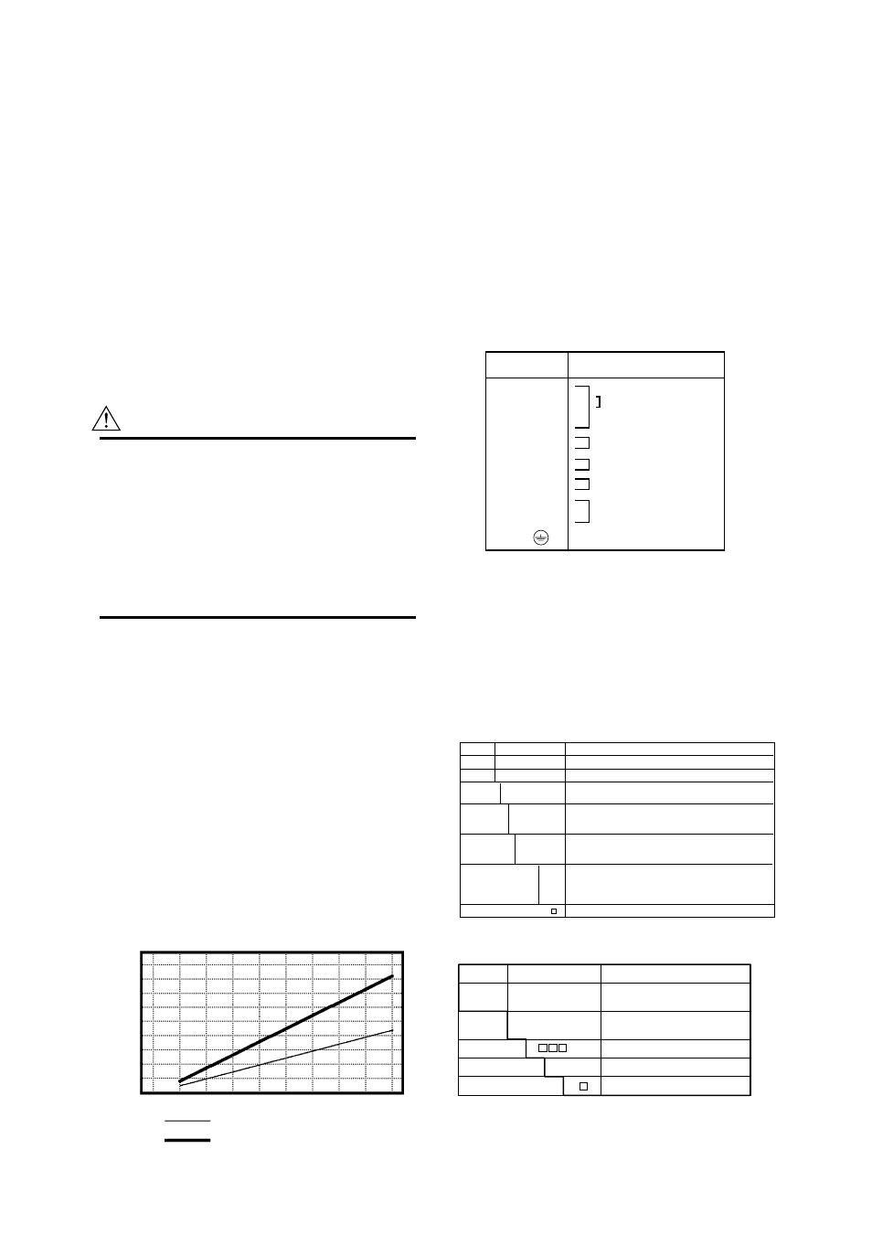
Supplied Power and Max. Cable Length for 24V
DC version:
Allowable cable length m(ft)
1000(3300)
900(2970)
800(2640)
700(2310)
600(1980)
500(1650)
400(1320)
300(990)
200(660)
100(330)
0
20
22
24
26
28
(V)
Cable cross section area: 1.25 mm
2
Cable cross section area: 2 mm
2
F01.EPS
Altitude at installation side:
Max.2000m above sea level
Installation category based on IEC1010:
II (See Note)
Pollution level based on IEC1010: 2(See Note)
Note: • The “Installation category” implies the regulation for
impulse withstand voltage. It is also called the
“Overvoltage category”.“II” applies to electrical
equipment.
• “Pollution level” describes the degree to which a
solid, liquid or gas which deteriorates dielectric
strength is adhering. “2” applies to a normal indoor
atmosphere.
Fuse: 2A 250V (Time-Lag type)
■
TERMINAL CONNECTION
Terminal
Symbols
Description
SA
A
B
SB
C
EX1
EX2
P+
P-
I+
I-
L/+
N/-
G
Flow signal input
T03-1.EPS
Protective grounding
A shield
Current output 4 to 20mA DC
Excitation current output
B shield
Common
Pulse, alarm or status output
Power supply and
Ground
PLS/ALM
OUT
CUROUT
POWER
SUPPLY
■
ACCESSORIES
Data sheet
1
Unit labels sheet
1
Hexagonal wrench
1
(for special screw of terminal cover/display cover.)
Plug 1 (in case of DC power supply version)
Mounting bracket
1set
■
MODEL AND SUFFIX CODE
Magnetic Flow Converter:
T05.EPS
Model
Suffix code
Description
SE14
Magnetic Flow Converter
Aux.Cod -J.........................
Always J
Output
D .....................
E .....................
4-20mA and Pulse or Alarm, Simultaneous 2-output (BRAIN)
4-20mA and Pulse or Alarm, Simultaneous 2-output (HART)
Indicator
NN ...............
H1 ................
H2 ................
Non Indicator
With Indicator
With Indicator and Setting SW
Power Supply -A1 .............
-A2 .............
-D1 ............
80 to 127V AC / 90 to 110 VDC
180 to 264 V AC
20.4 to 28.8V DC/AC
Electrical Connection
(Refer to Note1)
0 ......
2 ......
3 ......
4 ......
/ ...
JIS G1/2 Female
ANSI 1/2NPT Female
DIN Pg 13.5 Female
ISO M20X1.5 Female
Optional Codes
...........................
Note1 : Only ANSI 1/2NPT electrical connection is available for FM or CSA explosion proof type.
JIS G1/2 electrical connection is not available for any explosion proof type.
Dedicated Signal Cable:
Model
Suffix Code
Description
AM011
..............................
-0 ..........................
-4 ..........................
Dedicated cable for magnetic
flowmeter
Non termination
Terminated
Enter the length in m (Max 300m)
Style A
Number of end treatment parts
-L .........
*A ............
/C ..
End
treatment
Cable length
Style code
Optional specification
T10.EPS
Note 1 : A user provided two conductor cable is required for coil excitaiton.
Note 2 : The maximum temperature for the signal cable is 80
؇
C(176
؇
F).