4 dc connections, 5 wiring ports, Dc connections -3 – Yokogawa ADMAG AXF User Manual
Page 10: Wiring ports -3, Stranded wire; 0.5 to 2.5mm
IM 1E10C1-E
3-3
3. INSTALLATION
(2) Power, Excitation, or Output Cable
Power Cable
• Crimp-on Terminal
• Green/Yellow covered conductors shall be used only
for connection to PROTECTIVE CONDUCTOR
TERMINALS.
• Conform to IEC277 or IEC245 or equivalent
national authorization.
Excitation or Output Cable
• Please use Polyvinyl chloride insulated and sheathed
control cables (JIS C3401) or Polyvinyl chloride
insulated and sheathed portable power cables (JIS
C3312) or equivalents.
Outer Diameter
• 6.5 to 12mm in diameter (10.5 to 11.5 mm for
waterproof gland / ECG, /ECU)
Nominal Cross Section
• Single wire; 0.5 to 2.5mm
2
, Stranded wire; 0.5 to
2.5mm
2
60
(2.4)
85
(3.3)
EX1
EX2
EX1
EX2
On the converter side
On the flow tube side
F030204.EPS
Unit: mm (inch)
Figure 3.2.4
End Treatment of Excitation Cable
3.2.4
DC Connections
(1)Connecting Power Supply
IMPORTANT
In case of 24VDC power supply, AC power
supplies or reversed polarities cannot be con-
nected. It will cause the fuse to burn out.
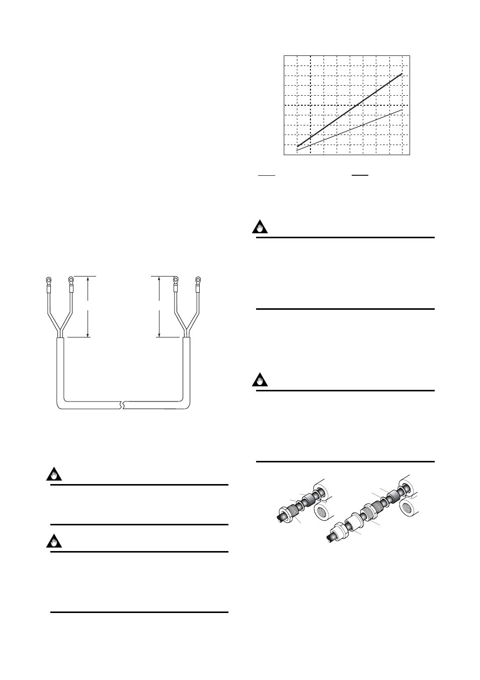
IMPORTANT
In case of 24VDC power supply, the specifica-
tion for the supply voltage is 24VDC (-15 to
+20%), but the input voltage of the converter
drops due to cable resistance so it should be
used within the following range.
Supply Voltage and Cable Length
1000
(3300)
900
(2970)
800
(2640)
700
(2310)
600
(1980)
500
(1650)
400
(1320)
300
(990)
200
(660)
100
(330)
0
Allowed
cable
length
m(ft)
20
22
24
26
28
Usable range E(V)
Cable cross section area : 1.25mm
2
Cable cross section area : 2mm
2
F030205.EPS
Figure 3.2.5
Supplied Power and Cable Length
(2)Setting Power Supply Frequency
IMPORTANT
In case of DC power supply, the frequency of
the power supply has to be adjusted. Please
adjust for the local power frequency. The power
supply frequency is set in parameter B12 (or
Power freq for HART). Refer to 5.4, 6.5.4, or
7.3.4 for data setting procedure.
3.2.5
Wiring Ports
Please select the most suitable standard of wiring
procedure for the wiring ports by customer’s own.
(1)Using the Waterproof Gland
IMPORTANT
To prevent water or condensate from entering
the converter housing, waterproof glands are
recommended. Do not over-tighten the glands or
damage to the cables may result. Tightness of
the gland can be checked by confirming that the
cable is held firmly in place.
Tightening gland
Washer
Gasket
Water-proof gland(/ECG)
Gasket
G1/2
F030206.EPS
Water-proof gland with union joint(/ECU)
Washer
Tightening gland
Figure 3.2.6
Waterproof Gland
(2)Conduit Wiring
In case of conduit wiring, please use the waterproof
gland to prevent water flowing through the conduit
pipe into the wiring connection.