3 csa, Csa -3 – Yokogawa ADMAG AXF User Manual
Page 106
IM 1E10C1-E
12-3
12. EXPLOSION PROTECTED TYPE INSTRUMENT
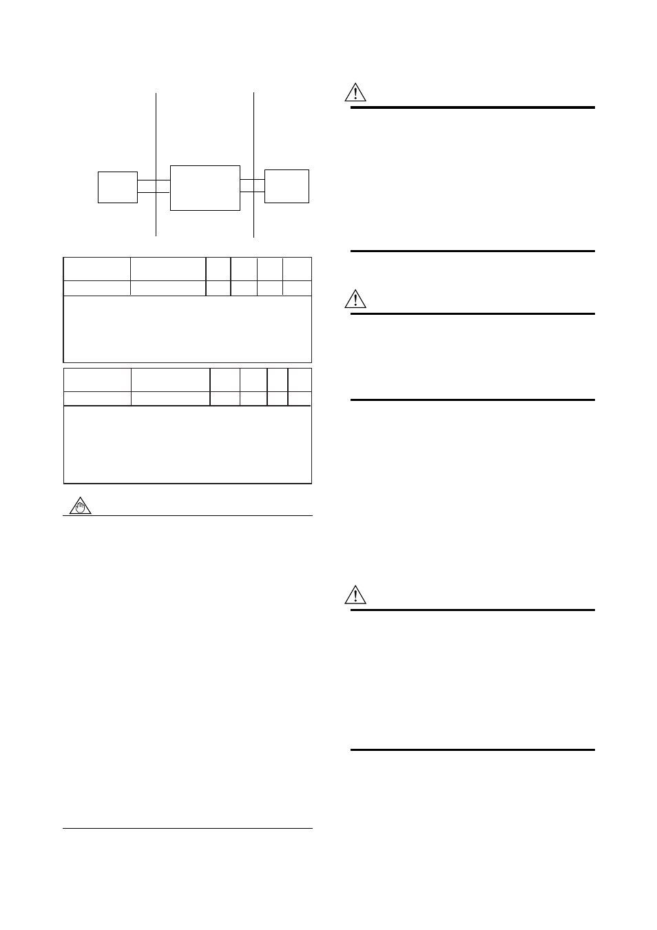
(2) Wiring (Following contents refers "DOC.
No. NFM008-A13 P.1 and P.2")
Hazardous(Classified)
Location
Class I, Division 2
Groups A, B, C, D
Hazardous(Classified)
Location
Class I, Division 2
Groups A, B, C, D
Associated
Apparatus
Nonhazardous
Location
Model SE14 Magnetic
Flow Converter
Control
Equipment
(Note 1)
(Note 3)
(Note 4)
(Note 5)
Nonincendive Field Wiring Parameters:
Output signal
Analog output
Signal name
Current Output
Voc
(V)
19.7
Isc
(mA)
21.6
Ca
(
µ
F)
0.3
La
(mH)
10
The nonincendive field wiring concept allows
interconnection of two FM Approved Nonincendive
Apparatuses with nonindendive field wiring parameters
not specifically examined in combination as a system
when:
Voc
Ϲ
Vmax, Isc
Ϲ
Imax, Ca
м
Ci+C cable, La
м
Li+L cable
Input signal
Contact output
Signal name
Transistor Output
Vmax
(V)
30
Imax
(mA)
135
Ci
(
µ
F)
0.1
Li
(mH)
0
The nonincendive field wiring concept allows
interconnection of two FM Approved Nonincendive
Apparatuses with nonindendive field wiring parameters
not specifically examined in combination as a system
when:
Voc or Vt
Ϲ
Vmax, Isc or It
Ϲ
Imax,
Ca
м
Ci+C cable, La
м
Li+L cable
NOTE
1. Control epuipment connected to the Model
SE14 magnetic flow converter must not use or
generate more than 250V rms or V dc.
2. Installation should be in accordance with the
National Electrical Code ANIS/NFPA 70.
3. The configuration of associated Apparatus
must be Factory Mutual Reseach Corporation
Approval under Nonincendive Field Wiring
Concept or be a simple apparatus (a device
which can neither generate nor store more
than 1.2V, 0.1A, 25mW, or 20 micro-J, ex.
Swithces, thermocouples, LED's and RTD's).
4. Associated Apparatus manufacture's
installation drawing must be followed when
installing this equipment.
5. Associated Apparatus connection is
representative of each input and output signal
connection. Each signal shall be wired in a
separate shielded cable.
6. No revision to drawing without prior Factory
Mutual Reseach Corporation Approval.
(3) Operation
WARNING
• DO NOT DISCONNECT WHILE CIRCUIT IS
LIVE UNLESS LOCATION IS KNOWN TO BE
NONHAZARDOUS.
• NI CLI DIV2, GPS ABCD WITH
NONINCENDIVE FIELD WIRING
PARAMETERS TO CLI DIV2, GPS ABCD PER
DWG NFM008-A13 P.1 & P.2. (Refer to (2))
• Do not connect BRAIN TERMINAL or HART
Communication in Hazardous locations.
(4) Maintenance and Repair
WARNING
The instrument modification or parts replacement
by other than authorized representative of
Yokogawa Electric Corporation is prohibited and
will void the approval of Factory Mutual Reseach
Corporation.
12.3 CSA
(1) Technical Data
Class I, Groups B, C & D; Class II, Groups E, F &
G; Class III; Encl Type 4X
Electrode Circuit : 41V max. 6//6.25Hz
Temperature Code : T6
Ambient Temperature : -20 to +60
°
C
(2) Wiring
WARNING
• All wiring shall comply with Canadian Electrical
Code Part I and Local Electrical Code.
• Note a warning label worded as follows.
Warning : A SEAL SHALL BE INSTALLED
WITHIN 50cm OF THE
ENCLOSURE.
UN SCELLEMENT DOIT ÉTRE
INSTALLÉ À MOINS DE 50cm DU
BOÎTIER.